Download
1 / 38
660 likes | 2.23k Views
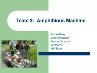
Amphibious Vehicle. 7 th Hour AET Curt Bagne, Phil Rockwell, Mike Schwanitz, Brantly Fulton, Austin Leske, Austin Duffy, Nigel Agboh. Hull Problem Statement.

E N D
Amphibious Vehicle 7th Hour AET Curt Bagne, Phil Rockwell, Mike Schwanitz, Brantly Fulton, Austin Leske, Austin Duffy, Nigel Agboh
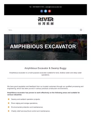
Hull Problem Statement • To successfully design, fabricate and build a hull that can be used implicated into an amphibious vehicle. This hull should be light, durable and within a reasonable price. To stay afloat, the volume of the hull needs to be greater than the mass of it.
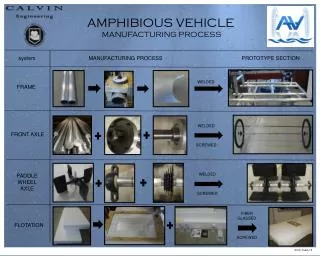
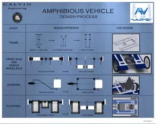
Performed a matrix for the hull design and the Flat bottom or Jon boat won. Sketched on paper and in CAD possible designs and determined approximate length and width dimensions. Collaborated with Land and Water groups to discuss design. Purchase a used boat hull for a reasonable price and modify it. Install a support frame/structure with crossbars around the rim of the hull to minimize wear and weight on the thin aluminum of the hull. We will also need to drill holes through the hull for the axles for Land mode. A top priority of ours will be to properly seal any holes we drill in the hull so that the vehicle does not take on water. Build it as hydrodynamic as possible to maximize speed in water. Attach plastic drum pontoons to the sides to increase buoyancy and balance. Design Statement
Land Problem Statement • As a class we must design an amphibious vehicle. This means that the vehicle must be able to be driven on both water and land. As the land group we must design all the features of the vehicle to be used on land. We must design a drive train, choose the engine we will use, and come up with a steering system. We must also work with the water and hull groups in order for our designs to agree. While doing this we must solve any issue that may come up including sealing holes put into the boat. Once we have figured out the design and made a sketch and 3D prototype on CAD we must put together a PowerPoint presentation to present our design plan.
Land Design Statement • On the first day our whole class got together and discussed what basic design we wanted for the amphibious vehicle. We decided that a more conservative design was best in order for us to be able to finish the vehicle by May. For the land crew we had to follow this conservative design and come up with the simplest yet effective drive train out of a front wheel drive, rear wheel drive, four wheel drive, and three wheels. We made a design matrix to rate these three ideas on the criteria of safety, effectiveness, degree of difficulty, cost, and control. It turned out that a basic rear-wheel drive system was the best for the class’s conservative design. • After we came up with our system, we talked with the water and hull groups to CAD the basic boat structure off of all three of our designs. Using this basic boat shape with set dimensions we drew a sketch of everything that would be included in the boat for our drive train. As we did the sketch we looked up engines we could use and we looked up the different things we could use to prevent water from coming into the boat through the axels. We decided it would be best to use the existing diesel engine on the go-kart to try and stick to our environmentally friendly theme we had with the go-kart. Also the engine has enough horsepower and torque to power the vehicle on land. To solve the leaking problem we came across what is called a stuffing box. This is basically a box that we put around the axel at the point where the hole in the boat is. This “box” would then be stuffed with rope and or some fluid that repels water like oil and welded to the side of the boat. The stuffing box is an easy solution to this problem and can be handmade making it cheap.
Land Design Statement Cont. • Once that was figured out we designed a steering system that we could use. This steering system uses a steering column with a tab that protrudes out of the top. This tab connects to two shafts that also connect to the wheels near the outside. As the wheel is rotated, the column rotates the tab. When the tab is rotated, the distance between the top of the tab changes. This change pushes the shafts to either the left or right. The shafts then push the wheels which are mounted on hinges to the side, steering the vehicle. With all this done we finished up on CAD and made IDWs. We then got together with the other groups and put everything together on one assembly to create a rough model of our amphibious vehicle.
Stuffing Box A stuffing box, or packing gland, is used around a propeller shaft at the point it exits a boat's hull underwater. It is the most common method for preventing water from entering the hull while still allowing the propeller shaft to turn. In a conventional stuffing box, the seal itself is provided by packing rings, or a square cross-sectioned rope, made of greased flax, which is packed or wound tightly around the propeller shaft, and compressed in place with a threaded nut and spacer. The box may also be fitted with an opening for periodic insertion of grease between the rings, and sometimes with a small grease reservoir. Our design requires 5 stuffing boxes, one for the propeller drive shaft, and 4 for the axels. We will be constructing our own stuffing boxes.
Water Problem Statement • Our objective is to design a fully functional vehicle that has both land and water transportation capabilities, making it amphibious. This amphibious vehicle must be safe, structurally sound, hydrodynamic, able to be modified, and cost effective. The durability and size of this vehicle are on the forefront of issues that we face. The vehicle’s safety is also of the utmost concern. Since this amphibious vehicle will be modified and used by us, the students, we do not want to put safety and/or security in a compromising position. As part of the water team, our job is to make sure that when we go into the vehicle, it will still go. We, the water group, have to pick a propulsion design and work out all details pertaining to said system. We have to make sure that all our components work together and are assembled correctly. If they are not, the prop may not provide enough force to move the boat.
Problem Statement Cont. • The hull’s buoyancy and ability to float will dictate what propeller we buy because the kind of prop we use will affect the speed and size of our amphibious vehicle. Our most difficult task as the water group or any other group on this team will be to design each of our parts in harmony and hopefully allow us to bring everything together without having to modify designs. The overall cost which we are limited to is about $3000. We will have to choose our parts wisely in order to complete our vehicle.
Water Design Statement • As the water group, we were posed with the challenge of designing and building the propulsion system of our vehicle while it is in the water. During our research, we came up with 4 different designs: tunnel design (regular propeller), tunnel design (surface piercing propeller), outboard engine, and water jet. To choose the best design for our needs, we created a design matrix to grade them in the following categories: complexity, cost, size, safety, speed, and durability. The winning design was the regular tunnel design. This design scored in the top of every category. It’s a relatively simple design, although not as simple as the outboard engine, that uses generic parts and is housed within a cutout in the hull. All of the other designs, with the exception of the outboard motor, require specific parts that could cost up to $450 for just one of their small parts. In using this design, we won’t have to worry about debris getting caught in the prop due to it’s location in the hull. If we were to use the outboard engine, we would have to constantly monitor its status and mountings. We also don’t have to worry about safety around the propeller while it is still spinning.
Water Design Statement Cont. • For the regular tunnel design, we would require a shaft, a motor with about 20 horsepower, extra sheet metal, propeller, and a means to make a water seal between the area between the shaft and the hole in the hull it goes through. We would put the motor behind the driver’s seat and extend the shaft from the motor through the back of the housing and into the water. The seal there is crucial. if it lets in water, our vehicle may sink. There will be rudders on the back to direct the flow from the propeller thus steering the boat.
Total Cost • Hull Group- 460.98 • Land Group- 716 • Water Group- 1026.01 • Total- 2202.99
Conclusion • Our design plan is exact, and will be executed in a timely manner • The design is simple, but effective, and will meet the task of operating on land and water • We will complete our project within the budget constraints