Download
1 / 31
330 likes | 797 Views
Outline. BackgroundResearch objectivesMach 8 facilityRoughness geometry PIV technique ResultsSmooth plateDiamond mesh rough plateDiamond mesh rough plate Conclusions Future work. Background. For flows Mach > 5, the general features of the mean flow behavior are reasonably well known, with a focus on surface data -- pressure, heat transfer, skin friction (Roy and Blottner, 2006) The mean flow, when transformed according to Van Driest, appears to follow the incompressible scaling and in1141

E N D
1. Effect of Roughness on a Turbulent Boundary Layer in Hypersonic Flow Dipankar Sahoo, Marco Schultze1 and Alexander J. Smits
Princeton University and 1University of Stuttgart
Supported by NASA Cooperative Agreement NNX08AB46A
39th AIAA Fluid Dynamics Conference
June 22-25, 2009, San Antonio, TX
3. Background For flows Mach > 5, the general features of the mean flow behavior are reasonably well known, with a focus on surface data -- pressure, heat transfer, skin friction (Roy and Blottner, 2006)
The mean flow, when transformed according to Van Driest, appears to follow the incompressible scaling and independent of Mach number.
4. Background Accurate and reliable turbulence measurements are difficult to make in supersonic flow; the difficulties are greater at higher Mach numbers (Smits & Dussauge, 1995)
Very few turbulence measurements exist for Mach > 5. Examples include:
Owen & Horstman (1972)
Constant temperature, two-component hot-wire measurements, including auto and cross-correlations, at Mach 7.0, Re? = 8500
Berg (1977)
Constant current, one component hot-wire measurements, at Mach 6.0, Re? = 14000 - 16000
McGinley, Spina & Sheplak (1994)
Constant temperature, one component hot-wire measurements at Mach 11, Re? = 6540, 12040
Much of the other hypersonic turbulence measurement work suffered from poor frequency response and/or suspect calibrations (McGinley, Spina & Sheplak, 1994)
5. Mach 7.2 (Owen et al., 1975) Hot-wires measure (?u)�
Use Strong Reynolds Analogy to deduce u�
Similarity expected to follow Morkovin, but high Mach number data does not support low Mach number data
6. Effects of roughness Only two sets of relatively complete turbulence data with roughness exist for high speed flow: Berg (1977) and Ekoto et al. (2008)
Berg (1977):
Mach 6, near adiabatic flow, square bar roughness (k+ = 33.8, ?/k = 25)
Equivalent sand grain roughness was half the value in subsonic investigations
Effective origin was below the crest of roughness element
Ekoto (2008)
Mach 2.86, adiabatic flow, diamond mesh and square block roughness (k+ = 100, ?/k = 15)
Diamond roughness caused local distortions which affected mean and turbulent flow. The effect of square roughness was much less significant.
For weak local distortions, inner-scaling captures the effect of roughness on turbulence without Morkovin�s scaling
7. Research objectives To improve our understanding of the effects of roughness on hypersonic turbulent boundary layers
Approach:
Obtain experimental data in hypersonic rough turbulent boundary layers (Mach 7.2) at DNS accessible Reynolds numbers (3260 < Re? < 4450)
Smooth plate
Two types of roughness: 3D Diamond mesh and 2-D square bars
Use Particle Image Velocimetry (PIV) to obtain velocity directly
Compare results with DNS (Pino Martin at Princeton)
8. Mach 8 facility Stagnation Temperature � up to 875K
Stagnation Pressure � up to 1500 psia
Useful Run time: 90-120 s
9. Mach 8 facility air supply 4 storage tanks (3000 psi)
8 existing air cooled Ingersoll Rand compressors
Automated
Provide enough air to run every second day
2 water cooled Worthington compressors
Refurbished and added to the main supply line
Manual control
Provide enough air to run every 6 Hrs.
10. Test model 2. 4 mm high tripwire
Painted black to reduce laser reflections: surface roughness < 2?m
Region of measurement:
380 mm from LE
FOV (Field of view) = 22 mm x 22 mm
12. Hot-wire anemometry will not give accurate results at high stagnation temperatures
Use Particle Image Velocimetry (PIV) for velocity field
Statistical data
Structural data
New Wave � Gemini PIV dual head laser
532 nm./100 mJ per pulse.
Jitter - � 0.5 ns
?t � 0.4 ?s
High speed PCO Cooke camera
Pixel resolution - 1600 x 1200
Short exposure � 500 ns
Berkeley box
Trigger the laser and camera
13. Challenge for PIV � high flow velocity, low density
14. PIV - seeding Seeding particles
TiO2 Particles
Manufacturer- specified diameter 50 nm
Effective diameter 400 nm
Particle injection
In the settling chamber upstream of the throat
Injection through 0.5� tube on centerline
Fluidized bed plus cyclonic separator (based on Clemens design)
Heating tape on fluidized bed reduces coalescence and improves particle dispersion
15. PIV - experimental set-up
16. PIV images Typical PIV images with diamond mesh and square bar roughness
FOV ~ 22 x 22 mm
17. PIV � data analysis Calibrate using precision grid
Discard images with unsatisfactory seeding density
Shift and rotate images to allow for tunnel movement (< 0.5?)
Three-step adaptive correlation (128 x 128, 64 x 64, 32x32 with 50% overlap)
Apply consistency filter (minimum 3 particles)
Apply velocity range validation filter
Discard data within 0.3mm of edge of each image
Non-dimensionalize velocity data before summing over multiple runs
18. Flow parameters
19. Smooth wall mean flow
20. Smooth wall turbulence
25. Rough wall mean flow
26. Rough wall wake similarity
27. Rough wall turbulence
28. Conclusions Mean flow comparisons were independent of Mach number in transformed coordinates
Turbulence intensities showed strong effect of compressibility
Mean velocity profiles for rough wall showed expected shift below log law
Transitional effect may have caused the decrease in wake parameter
Strong damping was observed in case of streamwise and wall normal velocity fluctuations
29. Need to increase the particle flow rate by increasing the size of the pipe in the seeding system
Need to perform further experiments with smaller roughness elements
Need to obtain a larger experimental database to establish the observations so far
Future Work
30. Acknowledgements NASA Cooperative Agreement NNX08AB46A
Program Manager: Catherine McGinley
Robert Bogart for assisting in setting up the experiments and running the tunnel.
QUESTIONS?
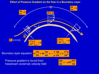
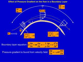
31. Boundary layer parameters