Download
1 / 18
220 likes | 334 Views
Disc Brakes Analysis. Mark Jetten Brian Richards Steve Weaver. Overview. Parts of disc brake and system Where disc brakes are used Materials and performance Analysis Uniform Pressure Uniform Wear. Parts of Braking System. Brake Pedal—force input to system from driver

E N D
Disc BrakesAnalysis Mark Jetten Brian Richards Steve Weaver
Overview • Parts of disc brake and system • Where disc brakes are used • Materials and performance • Analysis • Uniform Pressure • Uniform Wear
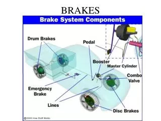
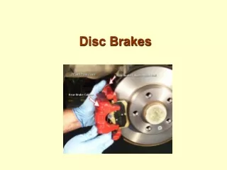
Parts of Braking System • Brake Pedal—force input to system from driver • Design gives a Mechanical Advantage • Master Cylinder—converts force to pressure • Pressure is used to move brake pads into place • Brake Pads—provide friction force when in contact with rotor • Works to slow or stop vehicle • Caliper—holds pads and squeezes them against rotor • Rotor—spins with wheel • When used in conjunction with brake pads, slows vehicle • Vents—help provide cooling to brake
B C A Mockup • A) Master cylinder • B) Pedal • C) Vents
Mockup continued • D) Brake pads • E) Caliper • F) Rotor E F D
Uses of Disc Brakes • Disc brakes are often on the front (and sometimes on the rear) wheels of cars • Do the real work of braking • Unlike drum brakes, do not self-energize
Materials • Different materials have different coefficients of friction • Pad material can be chosen for performance or to create a balance between performance and durability
Materials Continued • Asbestos brakes were used for years because of their extremely high friction coefficient, but advances in science has shown that it is a cancer causing substance. • Performance pads often include small pieces of metal in the pads to aid in the pads stopping power. The metal needs to be softer than the rotor, to ensure that the rotor is not damaged over long periods of use. • The friction coefficients in the table are representative of dry conditions. If the rotor and pad are moist, the systems stopping power is greatly reduced until the moisture can be burned off.
Caliper Operation Caliper • Step 1: Force is applied to by driver to the master cylinder • Step 2: Pressure from the master cylinder causes one brake pad to contact rotor • Step 3: The caliper then self-centers, causing second pad to contact rotor Brake Fluid 1 2 3 Pads Rotor
Secondary Primary Fapplied Master Cylinder • Force is applied to brake pedal by driver • Primary piston moves, which in turn pressurizes fluid in front of the first piston. The secondary piston and primary piston are connected through a spring. As the primary piston moves, it causes the secondary piston to move and pressurize fluid in front of it. • The pressurized fluid in the brake lines then causes the brake pads to move into contact with the rotor. • The secondary and primary pistons are used to give the car essentially two braking systems. Each controls two wheels. If one of the systems were the fail, the other can still stop the car.
Analysis • Brakes analyzed similarly to clutches • Uniform pressure • Valid for new brakes • Actuating force is product of pressure and area • Uniform wear • Valid after initial wear occurs
Geometry of Contact Area F = Force on pads θ1, θ2, r1, r0 = Dimensions of brake pad
Force and Torque Equations • p = pressure • ri,o = inner, outer radius • θ1,2 = initial, final contact angle • f = friction coefficient F=Force on pads T=Torque generated by pads
Uniform Pressure • When brakes are new, p = pa = allowable pressure. • The equations thus look like this:
Uniform Wear • With older brake pads, axial wear can be assumed constant. The pressure is expressed as the maximum allowable pressure pa, which occurs at ri. • Thus, p = pari/r
References • Mechanical Engineering Design by Joseph Shigley • http://www.howstuffworks.com