Download
1 / 47
470 likes | 781 Views
USB Universal Serial Bus. Omid Fatemi Interface Design . Motivations. Connection of the PC to Telephone The USB provides a ubiquitous link that can be used across a wide range of PC-to-telephone interconnects. Ease of use Hot plug Port expansion

E N D
USBUniversal Serial Bus Omid Fatemi Interface Design
Motivations • Connection of the PC to Telephone • The USB provides a ubiquitous link that can be used across a wide range of PC-to-telephone interconnects. • Ease of use • Hot plug • Port expansion • The lack of a bi-directional, low-cost, low-to-mid speed peripheral bus has held back the creative proliferation of peripherals such as telephone/fax/modem adapters, answering machines, scanners, PDA’s, keyboards, mice, etc.
USB • Fast • Bi-directional • Isochronous • low-cost • dynamically attachable serial interface • consistent with the requirements of the PC platform of today and tomorrow
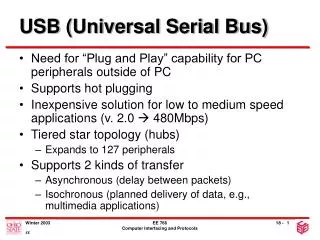
Goals for USB • The following criteria were applied in defining the architecture for the USB: • Ease-of-use for PC peripheral expansion • Low-cost solution that supports transfer rates up to 12Mb/s • Full support for real-time data for voice, audio, and compressed video • Protocol flexibility for mixed-mode isochronous data transfers and asynchronous messaging • Integration in commodity device technology • Comprehension of various PC configurations and form factors • Provision of a standard interface capable of quick diffusion into product • Enabling of new classes of devices that augment the PC’s capability.
Feature list • Easy to use for end user • Single model for cabling and connectors • Electrical details isolated from end user (e.g., bus terminations) • Self-identifying peripherals, automatic mapping of function to driver, and configuration • Dynamically attachable and re-configurable peripherals • Wide range of workloads and applications • Suitable for device bandwidths ranging from a few kb/s to several Mb/s • Supports isochronous as well as asynchronous transfer types over the same set of wires • Supports concurrent operation of many devices (multiple connections) • Supports up to 127 physical devices • Supports transfer of multiple data and message streams between the host and devices • Allows compound devices (i.e., peripherals composed of many functions) • Lower protocol overhead, resulting in high bus utilization
Feature list (con) • Isochronous bandwidth • Guaranteed bandwidth and low latencies appropriate for telephony, audio, etc. • Isochronous workload may use entire bus bandwidth • Flexibility • Supports a wide range of packet sizes, which allows a range of device buffering options • Allows a wide range of device data rates by accommodating packet buffer size and latencies • Flow control for buffer handling is built into the protocol • Robustness • Error handling/fault recovery mechanism is built into the protocol • Dynamic insertion and removal of devices is identified in user-perceived real-time • Supports identification of faulty devices
Feature list (con) • Relation with PC industry • Protocol is simple to implement and integrate • Consistent with the PC plug-and-play architecture • Leverages existing operating system interfaces • Low-cost implementation • Low-cost sub-channel at 1.5Mb/s • Optimized for integration in peripheral and host hardware • Suitable for development of low-cost peripherals • Low-cost cables and connectors • Uses commodity technologies • Upgrade path • Architecture upgradeable to support multiple USB Host Controllers in a system
USB System Description • USB interconnect • USB devices • USB host.
USB Interconnect • Bus Topology: Connection model between USB devices and the host. • Inter-layer Relationships: In terms of a capability stack, the USB tasks that are performed at each layer in the system. • Data Flow Models: The manner in which data moves in the system over the USB between producers and consumers. • USB Schedule: The USB provides a shared interconnect. Access to the interconnect is scheduled in order to support isochronous data transfers and to eliminate arbitration overhead.
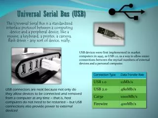
Throughput • Low speed • 1.5 Mbps • Full speed • 12 Mbps • High speed (in USB 2.0) • 480 Mbps • Dynamic mode switching • Clock encoding scheme: NRZI (Non Return to Zero Invert)
Power Distribution • Devices: • Bus-powered devices • Self-powered devices • Power management • Host based • Power events: • Suspend • Resume
Bus Protocol • Polled bus • Data transfers initiated only by host controller • Three packets: • Token packet • Type • Direction • Address • End point number • Data packet • Handshake packet • ACK • NAK
Transfer Model • Pipe • Stream pipes • No USB standard format • Message pipes • USB format • Request • Data • Status • End point zero • Default control pipe • Always exists
Data Flow Types • Control Transfers: • Used to configure a device at attach time and can be used for other device-specific purposes, including control of other pipes on the device. • Bulk Data Transfers: • Generated or consumed in relatively large and bursty quantities. • Interrupt Data Transfers: • Used for characters or coordinates with human-perceptible echo or feedback response characteristics. • Isochronous Data Transfers: • Occupy a pre-negotiated amount of USB bandwidth with a pre-negotiated delivery latency. (Also called streaming real time transfers).
USB Devices • All have endpoint zero • Hub • Function • Compound
Host Responsibility • Detecting the attachment and removal of USB devices • Managing control flow between the host and USB devices • Managing data flow between the host and USB devices • Collecting status and activity statistics • Providing power to attached USB devices.
Implementer Viewpoints • USB Physical Device: A piece of hardware on the end of a USB cable that performs some useful end user function. • Client Software: Software that executes on the host, corresponding to a USB device. This client software is typically supplied with the operating system or provided along with the USB device. • USB System Software: Software that supports the USB in a particular operating system. The USB System Software is typically supplied with the operating system, independently of particular USB devices or client software. • USB Host Controller (Host Side Bus Interface): The hardware and software that allows USB devices to be attached to a host.
Control Transfer Format • Setup packet • Data packet • Acknowledge packet • USB defined structure • Setup packet: 8 bytes • Maximum data payload size: • Full speed: 8, 16, 32 or 64 bytes • Low speed: 8 bytes
Control Transfer Constraints • Best effort • 10% frame time for control • Use also remaining 90% if no interrupt or isochronous transfer
Isochronous Transfers • Guaranteed access to USB bandwidth with bounded latency • Guaranteed constant data rate through the pipe as long as data is provided to the pipe • In the case of a delivery failure due to error, no retrying of the attempt to deliver the data. • Stream pipe • Uni-directional • Maximum data payload: 1023 bytes • Only in Full speed. • No more 90% of frame for isochronous, interrupt
Interrupt Transfers • Guaranteed maximum service period for the pipe. • Retry of transfer attempts at the next period, in the case of occasional delivery failure due to error on the bus. • Max. Payload size: • Full speed: 64 bytes • Low speed: 8 bytes • If there is sufficient bus time, for requested payload size the pipe is established.
Bulk Transfers • Large amount of data. • Access to the USB on a bandwidth-available basis. • Retry of transfers, in the case of occasional delivery failure due to errors on the bus. • Guaranteed delivery of data, but no guarantee of bandwidth or latency. • Stream pipe • Only in full speed • Max. Payload: only 8, 16, 32 or 64 bytes
Signals • Low and Full speed devices: • A differential ‘1’ is transmitted by pulling D+ over 2.8V with a 15K ohm resistor pulled to ground and D- under 0.3V with a 1.5K ohm resistor pulled to 3.6V. • A differential ‘0’ on the other hand is a D- greater than 2.8V and a D+ less than 0.3V with the same appropriate pull down/up resistors. • The receiver defines a differential ‘1’ as D+ 200mV greater than D- and a differential ‘0’ as D+ 200mV less thanD-. • The polarity of the signal is inverted depending on the speed of the bus. Therefore the terms ‘J’ and ‘K’ states are used in signifying the logic levels. In low speed a ‘J’ state is a differential 0. In high speed a ‘J’ state I s a differential 1.
Differential and Single Ended • Differential signals mostly for data • Certain bus states by single ended signals on D+, D- or both. • For example a single ended zero or SE0 can be used to signify a reset if held more than 10ms. • SE0 is holding down both D- and D+ below .3V • Low and Full speed • 90 Ohms +/- 15%