Download
1 / 42
460 likes | 838 Views
HVAC System Design. Mark Hydeman, P.E., FASHRAE Taylor Engineering, LLC mhydeman@taylor-engineering.com. it takes 2,000 to 3,000 times the volume of air to cool what you can with water!. With air, or…. with water?. How do you effectively fight a fire?. State of the present: with air.

E N D
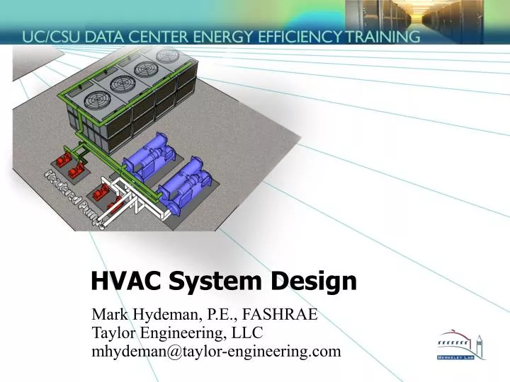
HVAC System Design Mark Hydeman, P.E., FASHRAE Taylor Engineering, LLCmhydeman@taylor-engineering.com
it takes 2,000 to 3,000 times the volume of air to cool what you can with water! With air, or… with water? How do you effectively fight a fire?
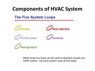
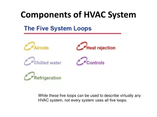
Air system design overview • Data center layout • Airflow configurations • Distribution: overhead or underfloor • Control: constant or variable volume • Airflow issues • Economizers • Humidity control issues
Server airflow front to back or front to back and top are recommended Data center layout Cold Aisle Hot Aisle © 2004, American Society of Heating, Refrigerating and Air-Conditioning Engineers, Inc. (www.ashrae.org). Reprinted by permission from ASHRAE Thermal Guidelines for Data Processing Environments. This material may not be copied nor distributed in either paper or digital form without ASHRAE’s permission.
Underfloor Supply Only 1 pressure zone for UF! Data center layout Cold Aisle Hot Aisle © 2004, American Society of Heating, Refrigerating and Air-Conditioning Engineers, Inc. (www.ashrae.org). Reprinted by permission from ASHRAE Thermal Guidelines for Data Processing Environments. This material may not be copied nor distributed in either paper or digital form without ASHRAE’s permission.
You can incorporate VAV on each branch Overhead Supply Data center layout Cold Aisle Hot Aisle © 2004, American Society of Heating, Refrigerating and Air-Conditioning Engineers, Inc. (www.ashrae.org). Reprinted by permission from ASHRAE Thermal Guidelines for Data Processing Environments. This material may not be copied nor distributed in either paper or digital form without ASHRAE’s permission.
Too hot Too hot Just right Too cold Typical temperature profile with UF supply Elevation at a cold aisle looking at racks There are numerous references in ASHRAE. See for example V. Sorell et al; “Comparison of Overhead and Underfloor Air Delivery Systems in a Data Center Environment Using CFD Modeling”; ASHRAE Symposium Paper DE-05-11-5; 2005
Typical temperature profile with OH supply Too warm Too warm Just right Elevation at a cold aisle looking at racks
Cold Aisle Caps Aisle capping Hot aisle lid End cap © APC reprinted with permission Cold Aisle Hot Aisle © 2004, American Society of Heating, Refrigerating and Air-Conditioning Engineers, Inc. (www.ashrae.org). Reprinted by permission from ASHRAE Thermal Guidelines for Data Processing Environments. This material may not be copied nor distributed in either paper or digital form without ASHRAE’s permission.
Cold Aisle Caps Aisle capping LBNL has recently performed research on aisle capping Cold Aisle Hot Aisle © 2004, American Society of Heating, Refrigerating and Air-Conditioning Engineers, Inc. (www.ashrae.org). Reprinted by permission from ASHRAE Thermal Guidelines for Data Processing Environments. This material may not be copied nor distributed in either paper or digital form without ASHRAE’s permission.
Airflow design disjoint • IT departments select servers and racks • Engineers size the fans and cooling capacity • What’s missingin this picture?
Airflow with constant volume systems • Hot spots • Higher hot aisle temperature • Possible equipment failure or degradation
Airflow with constant volume systems • Least hot spots • Higher air velocities • Higher fan energy • Reduced economizer effectiveness (due to lower return temperatures)
Airflow with constant volume systems • Note most of these observations apply to overhead and underfloor distribution • With constant volume fans on the servers you can only be right at one condition of server loading! • The solution is to employ variable speed server and distribution fans…
Airflow with variable volume systems Partial flow condition • Best energy performance but difficult to control
How Do You Balance Airflow? • Spreadsheet • CFD • Monitoring/Site Measurements Image from TileFlow http://www.inres.com/Products/TileFlow/tileflow.html, Used with permission from Innovative Research, Inc.
Thermal report From ASHRAE’s Thermal Guidelines for Data Processing Environments
Best air delivery practices • Arrange racks in hot aisle/cold aisle configuration • Try to match or exceed server airflow by aisle • Get thermal report data from IT if possible • Plan for worst case • Get variable speed or two speed fans on servers if possible • Provide variable airflow fans for AC unit supply • Also consider using air handlers rather than CRACs for improved performance (to be elaborated on later) • Use overhead supply where possible • Provide aisle capping (preferably cold aisles, refer to LBNL presentation for more details) • Plug floor leaks and provide blank off plates in racks • Draw return from as high as possible • Use CFD to inform design and operation
Air-Side Economizer issues • Hygroscopic dust • LBNL is doing some research on this • Design humidity conditions • See following slides
Design conditions at the zone © 2005, American Society of Heating, Refrigerating and Air-Conditioning Engineers, Inc. (www.ashrae.org). Reprinted by permission from ASHRAE Design Considerations for Data and Communications Equipment Centers. This material may not be copied nor distributed in either paper or digital form without ASHRAE’s permission.
San Francisco Upper Allowed Humidity Limit Design Target X Negligible time of possible concern for humidification Lower Allowed Humidity Limit (20%RH)
Los Angeles Upper Allowed Humidity Limit Design Target X Only a few hours of possible concern for humidification Lower Allowed Humidity Limit (20%RH)
Sacramento Upper Allowed Humidity Limit Design Target X Negligible time of possible concern for humidification Lower Allowed Humidity Limit (20%RH)
Lower humidity limit • Mitigate electrostatic discharge (ESD) • Recommended procedures • Personnel grounding • Cable grounding • Recommended equipment • Grounding wrist straps on racks • Grounded plate for cables • Grounded flooring • Servers rated for ESD resistance • Industry practices • Telecom industry has no lower limit • The Electrostatic Discharge Association has removed humidity control as a primary ESD control measure in their ESD/ANSI S20.20 standard • Humidity controls are a point of failure and are hard to maintain • Many data centers operate without humidification • This needs more research • And for some physical media (tape storage, printing and bursting) • Old technology not found in most data centers • It is best to segregate these items rather than humidify the entire data center
ESD control: floor grounding Image from Panduit, reprinted with permission
Water-Side Economizer Integrated Heat Exchanger in series with chillers on CHW side
Air-Side Economizers Provides free cooling when dry-bulb temperatures are below 78°F-80°F. May increase particulates (LBNL research indicates this is of little concern). Should be integrated to be most effective. Improves plant redundancy! Can work in conjunction with water-side economizers on data centers! Need to incorporate relief. Water-Side Economizers Provides low energy cooling when wet-bulb temperatures are below 55°F-60°F. Avoids increased particulates (and low humidity if that concerns you). Should be integrated to be most effective (see previous slide). Improves plant redundancy! Can work in conjunction with air-side economizers on data centers! Economizer Summary Both are proven technologies on data centers!
Collocation facility in the Bay Area Side by side designs in same facility over two phases Motivation for the second design was to reduce cost Case study was developed by Lawrence Berkeley National Laboratory (LBNL) Data Centers 8.1 and 8.2 Both sections at ~30% build-out during monitoring A case study of two designs
Phase 1 Data Center (8.1) 26,200 ft2 27 W/ft2 design Traditional under-floor design with CRAC units Air-cooled DX Humidity controls (45%-55%) Phase 2 Data Center (8.2) 73,000 ft2 50 W/ft2 design Under-floor supply from central AHUs with CHW coils Water-cooled plant Air-side economizers No humidity controls A tale of two designs: overview
~1/4 of the normalized energy Phase 1 Data Center (8.1) Phase 2 Data Center (8.2) Data normalized to computer loads A tale of two designs: a closer look Normalized efficiency metric:
Phase 1 Data Center (8.1) Around 2x the HVAC installed cost ($/ft2) Around 4x the energy bills (when normalized to server load) Acoustical problems Higher maintenance costs Lost floor space in data center due to CRACs Phase 2 Data Center (8.2) Preferred by the facility operators and data center personnel A tale of two designs: results
Two data centers: summary • What made the difference? • Airside economizers • No humidity controls • Water-cooled chilled water system • AHUs instead of CRAC units
Example CRAH Unit Comparison • 34% less water flow • 13% less fan energy • More if you consider the supply air temperature and airflow issues • Excess fan capacity on new units • 36% higher cost for units, but • Fewer piping connections • Fewer electrical connections • Fewer control panels • No need for control gateway • Can use the existing distribution piping and pumps (case study) • Can use high quality sensors and place them where they make sense • Possibly less turbulence at discharge?
Air cooling issues • Limitations on the data densities served (~200w/sf) • Air delivery limitations • Real estate • Working conditions • Hot aisles are approaching OSHA limits • Costly infrastructure • High energy costs • Management over time • Reliability • Loss of power recovery • Particulates
Take Aways • Use air- or water-side economizers where possible • Consider personal grounding in lieu of humidification • Consider AHUs as an alternative to CRACs • Consider VSDs on fans, pumps, chillers and towers • Refer to ASHRAE, LBNL and Uptime Institute for more recommendations