Download

1 / 7
70 likes | 286 Views
A NON-TRADITIONAL HIGH PERFORMANCE BROAD-BAND SEISMOMETER. PMD/eentec, USA www.eentec.com.

E N D
A NON-TRADITIONALHIGH PERFORMANCE BROAD-BAND SEISMOMETER PMD/eentec, USA www.eentec.com
Electro-chemical seismometers have many advantages: they are extremely robust, consume little power, operate over a wide temperature range, are fairly insensitive to installation tilts, and require no mass lock or mass centering. These seismometers are suitable for a range of applications: from educational uses to remote earthquake detection, borehole and ocean bottom installations. Major achievements: Ø Low to very low power consumption (down to 50mW) Ø Passband 0.008 – 50Hz Ø Dynamic range ~150dB Ø Noise level below NLNM between 0.05-5Hz Ø Clip level 20mm/s PMD/eentec OBS digital broadband
TRANSDUCER CELL Rather than attempt incremental improvements in a pendulum design, we chose a radically different approach to the mechanical system, which replaces the solid mass with a liquid electrolyte. The motion of this liquid generates an electrical output signal which is a function of the ground motion.
ELECTRODYNAMIC FEEDBACK SYSTEM Earlier MET sensors used an open-loop design. It is well known that force-balancing feedback allows for improving stability, extending dynamic and temperature range and guarantees perfect flatness of the response function. Significant efforts has been undertaken at PMD/eentec to develop a closed-loop electro-chemical seismometer. Non-traditional operational principles of a electro-chemical transducer require new approaches to the feedback system, even in the case of a traditional moving coil feedback. Hydrodynamic Response U=aL/Rh Transducer Cell I=Ucq Preamplifier, Filters, T-comp. V=I*K(T) a Differential driver Signal out Ground motion Moving Coil transducer Differentiator
R-1 ROTATIONAL SENSORS The Electro-chemical transducer can be used as a sensitive element for rotational sensors. True rotational seismometers with 3*10-7 rad/sec2/sqrt(Hz) resolution and >120 dB dynamic range are commercially available. Standard passband is 0.05-20Hz.
POSSIBLE APPLICATIONS FOR ROTATIONAL SEISMOMETERS • It has often been assumed that the movement of a small section of the ground surface is only translational. While this is approximately correct in the case of teleseismometry, the ground motion near the seismic source contains well pronounce rotational components. Our rotational sensors would make the general investigation of structures in earthquake-prone areas affordable. Data from structures, which are susceptible to collapse, or significant damage would enable engineers to understand better their nonlinear behavior and to predict failure modes of structures. • The unique feature of the rotational seismic sensor is its ability to retrieve a very weak signal generated locally in a very noisy environment (the spatial filtering capability). This is possible because the rotational seismometer is a differentiating type device. The experiment described below indicate that the spatial filtering phenomenon can be useful in many applications related to the seismic observations using rotational seismic sensors. • The purpose of the experiment, performed in June 2003 in Hanta-Mansijsk, Russia, was to detect and monitor the operating underground drilling equipment, using seismic sensors of different types. The sensors were installed on the earth surface. The low-cost vertical geophones (model CB-10, frequency range 5-120 Hz), broadband seismometers (4011, frequency range 0.033-50 Hz) and MET rotational seismic sensors R-1. Sensors were placed 600 meters from the drilling rig, while the operating drill was located approximately 1 km depth under the earth surface. The experiments were performed during the spring flood period and the drilling rigand sensors were located on two islands, separated by shallow water. The resultant spectra are shown in the following slide. • The following conclusions can be drawn from the data presented: • Low-cost vertical geophones did not detect the low-frequency signals, produced with the underground equipment and consequently are useless for the purpose of the experiment • The broadband seismometer recorded the peaks, corresponding to the translational motion of the drilling equipment (peaks at 1.1 Hz on the upper right corner and on the middle row plots). The proportions between signals, corresponding to different directions allow defining the direction to the drill. • Only the rotational sensor (lower left corner on the next slide) detect the frequencies corresponding the frequency of the drill rotation (0.8 Hz) and its second and third harmonics (1.6 and 2.4 Hz, correspondingly). It is worth mentioning that these peaks were not observed on the linear motion sensors plots, since they were masked by a background seismic noise, related with water surface oscillations, especially significant on windy days. This noise doesn’t affect the rotational sensor, due to the large size of the noise source and spatial filtration capability of the rotational sensor. The result of this experiment shows that rotational sensors have a great potential for remote monitoring of the underground drilling equipment.
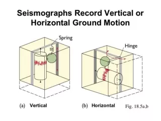
Experiment 1. Rotational sensor sensitivity axis is directed vertically Experiment 2. Rotational sensor sensitivity axis is horizontal and perpendicular to the direction to the derrick Experiment 3. Rotational sensor sensitivity axis is directed to the derrick