Download
1 / 37
370 likes | 849 Views
Overview of Power Electronics for Hybrid Vehicles P. T. Krein Grainger Center for Electric Machinery and Electromechanics Department of Electrical and Computer Engineering University of Illinois at Urbana-Champaign April 2007 Quick history Primary power electronics content

E N D
Overview of Power Electronics for Hybrid Vehicles P. T. Krein Grainger Center for Electric Machinery and Electromechanics Department of Electrical and Computer Engineering University of Illinois at Urbana-Champaign April 2007
Quick history Primary power electronics content Secondary power electronics content Review of power requirements Architectures Voltage selection and tradeoffs Impact of plug-in hybrids SiC and other future trends Overview
Hybrids date to 1900 (or sooner). U.S. patents date to 1907 (or sooner). By the late 1920s, hybrid drives were the “standard” for the largest vehicles. Quick History www.hybridvehicle.org www.freefoto.com
Revival for cars inthe 1970s. Power electronicsand drives reachedthe necessary levelof development earlyin the 1990s. Major push: DoE HybridElectric Vehicle Challengeevents from 1992-2000. Quick History eands.caltech.edu
Battery technology reaches an adequate level in late 1990s. Today: Li-ion nearly ready. Power electronics:thyristors before 1980. MOSFET attempts inthe 1980s, expensive (GM Sunraycer) IGBTs since about 1990. Quick History
Main traction drive inverter (bidirectional) Generator machine rectifier Battery or dc bus interface Charger in the caseof a plug-in Primary Power Electronics Content
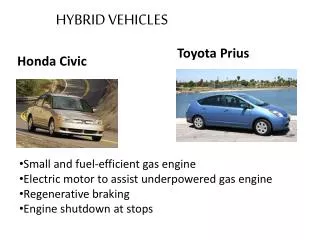
IGBT inverter fed from high-voltage bus. Field-oriented induction machine control or PM synchronous control. Traction Inverter
Voltage ratings: ~150% or so of bus rating Currents: linked to power requirements The configuration isinherently bidirectionalrelative to the dc bus. Field-oriented controlsprovide for positive ornegative torque. Traction Inverter C. C. Chan, “Sustainable Energy and Mobility, and Challenges to Power Electronics,” Proc. IPEMC 2006.
If a generator is present, it can employ either passive or active rectifier configurations. Power levels likely to be lower than traction inverter. Converter can be unidirectional, depending on architecture. Generator Rectifier
In some architectures, the battery connection is indirect or has high-power interfaces. Ultracapacitor configurations Boost converters for higher voltage Braking energy protection Battery/Bus Interface
With boost converter, the extra dc-dc step-up converter must provide 100% power rating. With ultracapacitors, the ratings are high but represent peaks, so the time can be short. Battery/Bus Interface
Major accessory drives Power steering Coolant pumps Air conditioning Conventional 12 Vcontent and interfaces On-board batterymanagement Secondary Power Electronics Content
Approach 1 kW each. Typically operating as a separate motor drive. Power steering one of the drivers toward 42 V. Air conditioning tends to be the highest power – run from battery bus? Major Accessories
About 1400 W needed for interface between high-voltage battery and 12 V system. Nearly all available hybrids use a separate 12 V battery. Some merit to bidirectional configuration, although this is not typical. Conventional 12 V Content
Few existing systems use active on-board battery management. Active management appears to be essential for lithium-ion packs. Active management is also required as pack voltages increase. A distributed power electronics design is suited for this purpose. On-Board Battery Management
Energy and power in a vehicle must: Move the car against air resistance. Overcome energy losses in tires. Overcome gravity on slopes. Overcome friction and other losses. Deliver any extra power for accessories, air conditioning, lights, etc. Power Requirements
Typical car, 1800 kg loaded, axle needs: 4600 N thrust to move up a 25% grade. 15 kW on level road at 65 mph. 40 kW to maintain 65 mph up a 5% grade. 40 kW to maintain 95 mph on level road. Peak power of about 110 kW to provide 0-60 mph acceleration in 10 s or less. 110 kW at 137 mph. Plus losses andaccessories. Power Requirements
Traction power in excess of 120 kW. Current requirements tend to govern package size. If this is all electric: Requires about 500 A peak motor current for a 300 V bus. About 300 A for a 500 V bus. Generator power on the order of 40 kW. Power Requirements
For plug-in charging, rates are limited by resource availability. Residential: 20 A, 120 V outlet, about 2 kW maximum. 50 A, 240 V outlet, up to 10 kW. Commercial: 50 A, 208 V, up to 12 kW. All are well below traction drive ratings. Power Requirements
Series configuration, probably favored for plug-in hybrid. Engine drives a generator, never an axle. Traction inverter rating is 100%. Generator rating approximately 30%. Charger rating 10% or less. Architectures
Parallel configurations, probably favored for fueled vehicles. Inverter rating pre-selected as afraction of total tractionrequirement, e.g. 30%. Similar generator ratingif it is needed at all. Source: Mechanical Engineering Magazineonline, April 2002. Architectures
Lower voltage is better for batteries. Higher voltage reduces conductor size and harness complexity. Extremes are not useful. < 60 V, “open” electrical system with limited safety constraints. > 60 V, “closed” electrical system with interlocks and safety mechanisms. Voltage Selection
Traction is not supported well at low voltage. Example: 50 V, 100 kW, 2000 A. Current becomes the issue: make it low. Diminishing returns above 600 V or so. 1000 V+ probably too high for 100 kW+ consumer product. Basic steps governed by semiconductors. Voltage Selection
600 V IGBTs support dc bus levels to 325 V or so. (EV1 and others.) 1200 V IGBTs less costly per VA than 600 V devices. Support bus levels to 600 V +. Higher IGBT voltages – but what values are too high in this context? Voltage Selection
First hybrid models used the battery bus directly. Later versions tighten thepackage with a voltageboost converter. Double V: ½ I, ½ copper,etc. Voltage Selection
Boost converter has substantial power loss; adds complexity. Cost tradeoff against active battery management. Can inverter current belimited to 100 A or less? Voltage Tradeoffs
More direct high battery voltage is likely to have advantages over boost converter solution. Battery voltages to 600 V or even 700 V have been considered. Within the capabilities of 1200 V IGBTs. Voltage Tradeoffs
Need sufficient on-board storage to achieve about 40 miles of range. This translates to energy recharge needs of about 6 kW-h each day. For a 120 V, 12 A(input) charger with90% efficiency, thissupports a 5 h recharge. Impact of Plug-In Hybrids
The charger needs to be bidirectional. This is a substantial cost add. Impact of Plug-In Hybrids
Single-phase version. Impact of Plug-In Hybrids
Easy to envision single-phase 1 kW car-mount chargers. Bidirectional chargers could double as inverter accessories. Notice that utility control is plausible via time shifting. Impact of Plug-In Hybrids
Home chargers above 10 kW are unlikely, even based on purely electric vehicles. Obvious limits on bidirectional flow that limit capability as distributed storage. Impact of Plug-In Hybrids
Power electronics in general operate up to 100°C ambient. HEV applications: liquid cooling, dedicated loop. Would prefer to be on engine loop. SiC and Future Trends
Si devices can operate to about 200°C junction temperature. SiC and GaN offer alternatives to 400°C. Both are high bandgap devices that support relatively high voltage ratings. SiC and Future Trends
More subtle but immediate advantage: Schottky diodes, now available in SiC for voltages up to 1200 V, have lower losses than Si P-i-N diodes. SiC and Future Trends
Fully integrated low-voltage drives. Higher integration levels for inverters ranging up to 200 kW. Better battery management. Future Trends