Download
1 / 61
610 likes | 1.03k Views
Components of an Electrical Circuit. Factors that influence resistance.

E N D
Factors that influence resistance • The five factors that determine the resistance of conductors are length, diameter, temperature, physical condition, and conductor material. A light bulb filament, motor windings or coil windings, and the bimetal elements in sensors are conductors. Also, the five factors apply to circuit wiring and working devices or loads. When two wires consist of the same material and diameter, the longer wire has greater resistance than the shorter wire. Wire resistance is listed in ohms per foot. Replacement wires must be the proper length.
Factors that influence resistance If two wires are the same material and length, the thinner wire has greater resistance than the thicker wire. Wire resistance tables list ohms per foot for wires of varying thicknesses. Replacement wires and splices must be the proper size for the circuit current. NOTE: Consider size and gauge when replacing wires. Those with 1, 2, and 3 are thicker with less resistance and more current capacity while those with 18, 20, and 22 are thinner with more resistance and less current capacity.
Factors that influence resistance In most conductors, resistance increases as wire temperature increases because electrons move faster and create heat. In most insulators, resistance decreases as temperature increases. Various test equipment can be used to measure temperature and resistance.
Factors that influence resistance Partially nicked or cut wire has high resistance in the damaged area. A kink in the wire, poor splices, and loose or corroded connections also increase resistance. Materials with free electrons are good conductors and have low resistance to current flow. Materials with bound electrons are insulators (poor conductors) and have high resistance to current flow. NOTE: Copper, aluminum, gold, and silver are good conductors. Rubber, glass, paper, ceramics, plastics, and air are insulators.
Stranded wire • The stranded-wire conductor uses wire made from copper covered with polyvinyl chloride (PVC) insulation. The PVC insulation prevents electrical shorts because the bare electrical wire does not touch other conductive materials. Circuit wires must have enough surface area to carry the amount of current needed to operate the load properly. Also, they must withstand vibration and bending. Stranded wire is rated according to the highest electrical current the wire can take without becoming too hot. Length helps determine wire size. The greater the distance from the source of electrical current, the greater the resistance to current flow. Larger sizes of wire can counter this resistance by providing a greater number of current paths to the load.
Stranded wire The American Wire Gauge System (AWGS) and the Metric Wire Gauge System (MWGS) are used to size wire. Both of these systems assign an identification number to electrical wire based upon wire diameter. • In the AWGS, the larger the number, the smaller the wire size. Identification numbers range from 22 gauge (small) to 000 gauge (large). The cross-section of a wire is measured in a unit called a circular mil, which is the equivalent area of a circle whose diameter is 0.001 in. • In the MWGS, the larger the number, the larger the wire size. Identification numbers range from 0.5 millimeters (small) to 4.0 millimeters (large). Individual wires are bound into wiring harnesses and routed throughout the vehicle. For an orderly wiring system, manufacturers cover wires with different insulation colors.
Stranded wire • The printed circuit board is a conductor. Copper is laminated to an insulating material. The copper is processed so that it forms individual strips, each of which becomes a current path for circuits.
Stranded wire • NOTE: The copper strips in printed circuit boards are thin and should be handled with care. Check for breaks in the printed circuit board where there is a bend.
Stranded wire • If the body of the vehicle is constructed of metal, it can be a conductor. To cut costs and reduce vehicle weight, manufacturers use the steel frame and metal body as a current path for some circuits. This is referred to as chassis ground or a 1-wire system.
Stranded wire • In early model cars, spark plugs were made of stranded copper wrapped in thick insulation. When radios were introduced, a change in spark plug wire construction became necessary. The force of electron flow is so great in spark plug wires that it causes a popping noise in the radio. To eliminate this noise, manufacturers use radio suppression wires in spark plugs. • Radio suppression wires are fiberglass cords saturated with carbon. Heavy silicone or vinyl insulates the central cord. • Because carbon is not as good of a conductor as copper, radio suppression wires generate less radio interference.
Stranded wire Special care should be taken when removing and installing spark plug wires. If stretched, the fiberglass cord within the spark plug wire can be easily damaged. • Carbon is used in a variety of conductors. It has a higher resistance to current flow than other conductors. Also, carbon can maintain current flow between stationary and rotating parts and resist wear that results from rubbing.
Types of electrical insulation • Electrical insulation keeps electron flow inside the conductor and prevents different conductors from making contact. PVC is the most common type of electrical insulation. NOTE: Insulation devices can be deceptive. A flat washer can be an insulation device. The technician must know where current Is supposed to flow within a circuit. • Glass and porcelain are used as insulation devices because they maintain resistance at high temperatures. These materials are used in spark plugs, oxygen sensors, and other applications that involve high temperatures and high voltage.
Types of electrical insulation • Bakelite, plastic, and alkyd are used as rigid insulation devices because they can be molded into almost any shape. A conductor can be embedded into these materials or placed in them after molding. The following are examples of how rigid insulation devices are used in different areas of the vehicle.
Types of electrical insulation • Insulating washers prevent current from grounding as it passes through other conductive materials. The following shows a stud inserted through the aluminum housing of an alternator. The insulating washers keep the stud from contacting the aluminum housing. • Conductors that lie close to each other are often coated with varnish to ensure that current does not leak from one conductor to the other. Any wrapped coil is coated with varnish.
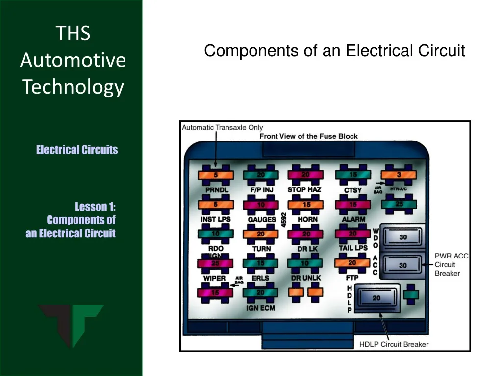
Types of circuit protection devices • Fuses, fusible links, and circuit breakers are located in the fuse block. These devices are designed to open the circuit when excess current flows through.
Types of circuit protection devices • The fuse is a zinc strip bonded between two endcaps. The zinc strip is encased in glass, plastic, or a ceramic sleeve. It is designed to destruct at a specific ampere of current flow. Minifuse Autofuse Maxifuse
Types of circuit protection devices Fuses are categorized by a letter system and number. The number indicates the maximum current-carrying capacity. The appearance of a blown fuse can indicate the cause of a circuit overload. • Small breaks in the zinc strip indicate a high-voltage surge or momentary current overload. • Large breaks in the zinc strip indicate a high-current overload, grounded conductor, or shorted load. • Vaporized breaks in the zinc strip indicate a grounded circuit.
Types of circuit protection devices • The fusible link is a short piece of alloyed wire. The alloy causes the fusible link to destruct at a specific ampere of current flow. Fusible links are rated by wire gauge size and amperes. Fusible links are usually located near the terminal connection to the power source. Fusible links sometimes have a molded flag at the terminal end, indicating gauge size and ampere rating. Locating a blown fusible link can be difficult. Insulation surrounding a destroyed fusible link appears undamaged even though the insulation can be somewhat soft. The break can be located by squeezing or pulling gently on the wire.
Types of circuit protection devices CAUTION: Do not bypass a blown fusible link to restore a circuit. Replace the fusible link with wire that is the correct gauge and appropriate length. • The circuit breaker is a thermally operated device. A bimetal strip keeps contact points on the circuit breaker closed. • When current flow through the bimetal strip becomes too great, it overheats and bends to open the contact point and disrupt circuit operation. • When the bimetal strip cools, it contracts and closes the contacts to reactivate the circuit.
Types of circuit protection devices • If circuit overload persists, the circuit breaker again overheats and opens, causing the circuit to be intermittently on and off. Continuous action of the circuit breaker can result in premature failure. Circuit breakers are rated according to their maximum current draw before opening.
Types of circuit protection devices Manual circuit breakers can be reset in two ways. One way is to push a button located on the circuit breaker. The other way is to disconnect power to the circuit breaker and wait for it to cool down. The positive temperature coefficient (PTC) circuit breaker is wired inside a load component like a wiper motor or power window motor. When current exceeds design limits, resistance of the PTC circuit breaker increases until the circuit is opened. The PTC circuit breaker resets once the high current condition of the circuit is no longer present.
Circuit load devices and how they function • An electrical component must meet three requirements to be considered a load device. The device must have some current resistance to ensure the force device is not depleted too rapidly. The resistance of a load device must not be great enough to prevent current flow within the circuit. The load must perform some observable function, such as producing light, heat, or magnetism.
Circuit load devices and how they function • Incandescent bulbs are the most common source of light in a vehicle. Incandescent bulbs are illumination loads. Incandescent bulbs are either single filament or multiple filament. • A single-filament incandescent bulb has one insulated contact. The bulb is grounded through its socket. In a smaller single-filament bulb, a separate contact provides ground. • A multiple-filament incandescent bulb has two heating filaments. It is grounded by a socket or by a separate terminal or contact.
Circuit load devices and how they function A numbering system categorizes incandescent bulbs according to their use. The lower the resistance of a filament, the greater the current flow through it and the brighter the light produced.
Circuit load devices and how they function • Wound coils are known as coil-wrapped loads. These are used in electrical load devices, such as starters, relays, ignition coils, wiper motors, gauges, and alternators. Wound coils function according to three basic magnetic principles. If a current is being forced through a conductor, a magnetic field is created around that conductor. To increase the strength of the magnetic field, the conductor is wrapped into a coil. Also, increasing current flow through the conductor or placing an iron core within the coil increases the strength of the magnetic field. A wrapped conductor that produces a magnetic field when current passes through it is a load device.
Circuit load devices and how they function • The maximum current-carrying capacity of some conductors is balanced with the amount of heat the conductor can safely handle. The conductor produces heat as current flows. These conductors are known as thermal loads. Nichrome is the most common type of thermal load. It can produce intense heat from large amounts of current flow without sustaining damage. The heat produced by thermal loads can perform a variety of functions, such as defrosting windows and operating warning gauges.
Capacitors and how they function • A capacitor uses an electrostatic field to absorb or store an electrical charge. A capacitor in a circuit builds up a charge on its negative plate. Current flows until the capacitor charge and power source are equal. The capacitor charge is then stored until it is discharged through another circuit. CAUTION: Handle capacitors with care. Once charged, they can cause shocks long after power is removed. • The three types of capacitors are the ceramic, paper and foil, and electrolytic. The ceramic capacitor is used for electronic circuits.
Capacitors and how they function The paper and foil capacitor is used for noise containment in charging and ignition systems. The electrolytic capacitor is used for turn signal lights.
Capacitors and how they function • Capacitors are rated in microfarads. The rating is stamped on the case. Make sure to choose the proper capacitor rated for the maximum expected voltage.
Capacitors and how they function • A resistor is a mechanical or semiconductor device that reduces the electrical force in a circuit. All loads reduce electrical force to some degree. The force reduction across a load is called voltage drop. When electrons are forced through a coil, light bulb, or heater, they are converted into magnetism, heat, light, or motion. The resistor cases voltage drop to occur across itself. It differs from other load devices because its single purpose is to produce voltage drop, causing the circuit to operate at lower voltage. NOTE: Heat and magnetism produced by the resistor have no practical use.
Capacitors and how they function The three classifications of resistors are fixed-value, stepped, and variable. • The two types of fixed-value resistors are wire-wound and carbon. Wire-wound resistors are made with coils of resistor wire. They are accurate and heat stable. The resistance value is marked on them.
Capacitors and how they function Carbon resistors are mixed with binder. The more carbon, the lower the resistance. Some have the resistance value stamped on them while others are rated in watts of power. Most have color-coded bands to show resistance value. A carbon resistor with four bands – red, green, black, and brown from left to right – is sized as follows: • The first two bands set the digits. Red is 2 and green is 5. • The next band represents the number of zeros. Black is 0 zeros. So, the resistor has a base value of 25W. • The last band represents tolerance. Brown is 1%. So, the resistance value is 25 ohms plus or minus .25 ohms, or 24.75W to 25.25W.
Capacitors and how they function • Two or more fixed resistance values are contained in stepped or tapped resistors. The different resistances, which are either carbon or wire, are connected to different terminals in a switch. Different resistance values are placed in the circuit as the switch is moved.
Capacitors and how they function • The three types of variable resistors are rheostats, potentiometers, and thermistors. The rheostat dims or brightens the dash panel lighting and is located on the headlight switch. One end of the rheostat is connected to the fixed end of a resistor. The other end is connected to a sliding contact on the resistor. Rotating the control increases or decreases resistance. The potentiometer is a device that varies resistance according to the movement of mechanical parts. The first two connections of a potentiometer are made at each of the resistor ends. The last connection is made on a sliding contact. Rotating the control increases or decreases resistance in the circuit.
Capacitors and how they function The thermistor is a device that varies resistance according to temperature. Negative temperature coefficient (NTC) thermistors and positive temperature coefficient (PTC) thermistors can be used in the same vehicle. • Each of these thermistors change resistance with an increase in temperature. In NTC thermistors, resistance decreases as temperature increases. In PTC thermistors, resistance increases as temperature decreases.
Circuit control devices and how they function • A circuit control device controls the amount of current flowing through a circuit. It also ensures that current flows at the proper time. A circuit control device performs one of three essential functions. The circuit control device opens or closes the circuit by mechanical or electronic means. The circuit control device relays a large rate of current by means of a small current signal. The circuit control device increases or decreases current rate. • The most common circuit control device is a switch. The switch has two or more sets of contacts. Opening the contacts is referred to as breaking the circuit. Closing the contacts is called making the circuit.
Circuit control devices and how they function Poles refer to the number of input circuit terminals and throws refer to the number of output circuits. • A single-input (pole), single-output (throw) switch is called a single-pole, single-throw switch (SPST). • A single-input (pole), double-output (throw) switch is called a single-pole, double-throw (SPDT) switch. • A multiple-input (pole), multiple-output (throw) switch is called a multiple-pole, multiple-throw (MPMT) switch. Switches can be push-pull, rotary, or momentary on/off.
Circuit control devices and how they function The six different types of switches are the SPST, SPST momentary contact, SPDT, MPMT, mercury, and temperature-sensitive.
Circuit control devices and how they function • A relay is a remote-control switch that uses a small amount of current to control a large amount of current. A standard relay has a control circuit and a power circuit.
Circuit control devices and how they function The power source supplies current to the control circuit. Current then flows through a switch and an electromagnetic coil to ground. The power source supplies current to the power circuit. Current flows to an armature, which can be attracted by the magnetic force on the electromagnetic coil. • A solenoid is an electromagnetic switch that has a moveable core to convert current flow into mechanical movement.
Circuit control devices and how they function In the pulling-type solenoid, the magnetic field pulls the core into a coil. A pull-in coil pulls the core into the coil, and a hold-in coil holds the core in place. In a push-pull-type solenoid, a permanent magnet is used for the core. By changing current flow direction, the core is pulled in or pushed out. This type of solenoid is used on electric door locks.
Circuit control devices and how they function • Comfort and convenience luxuries are provided using electronic devices and systems called solid-state electronics. These work through the control of electricity and do not have electromechanical parts. Current flows through a semiconductor. This movement produces an electrical signal that may be transmitted, amplified, or utilized in special circuits in order to perform logical decision-making functions. • Semiconductors have the ability to act like conductors or insulators. While their resistance is higher than conductors like copper or iron, it is lower than insulators like glass or rubber. Semiconductors have special electrical properties. By mixing certain substances, conductivity can be increased. Light, temperature, and mechanical pressure can alter resistance. By passing current through semiconductors, light is produced.
Circuit control devices and how they function • The diode controls the direction of current flow but not the rate of current flow. The diode acts as a one-way electron check valve that allows current flow in one direction but stops current flow coming from the other direction.
Circuit control devices and how they function • The zener diode is similar to the diode. Under normal conditions, the zener diode allows current flow in one direction and stops current flow in the opposite direction up to a point. If opposing current flow is forced hard enough, the zener diode will break down, allowing current flow in either direction. When the opposing current flow decreases, the zener diode again functions as a diode.
Circuit control devices and how they function • The light-emitting diode (LED) is a diode that produces light. Transparent epoxy cases are produced with LEDs, so they can emit the light they generate when forward biased. Depending on how the material is doped, the color of the light given off by a LED can be red, green, or infrared.
Circuit control devices and how they function As in a diode, the LED allows current flow only in one direction. • The forward bias voltage drop is 1.5 volts to 2 volts, which is much higher than a diode. • The forward bias current through the LED must be kept under control or damage will result. Some advantages of LEDs are longer life, cooler operation, lower voltage requirements, and the ability to produce the same amount of light as an incandescent bulb while using less power.
Transistors and how they function • Transistors are made from positive-type (P-type) and negative-type (N-type) materials. They utilize the same principles as the diode. Transistors have two positive/ negative junctions. A transistor performs more functions than a diode, such as operating as a solid-state switch or amplifier. When used in a vehicle, the transistor is most commonly used as a switch. • Transistors, such as the AC blower motor, are used as amplifiers to control the speed of the electric motor. • Transistors are used as solid-state switches to control actuators, such as electronic fuel injectors.
Transistors and how they function • The three parts of a bipolar transistor are the emitter, base, and collector. The two types of bipolar transistors are the positive-negative-positive (PNP) and the negative-positive-negative (NPN). Transistor type is determined by the type of material used to make each of the three transistor parts.