Download
1 / 19
240 likes | 425 Views
Design of an Obstacle Avoidance Vehicle. Frank Scanzillo EECC657. Objectives. Detection and avoidance of obstacles Detection of and navigation toward light beacon (final destination of vehicle) . Specifications. Maximum distance from tank to beacon: 7.8 m

E N D
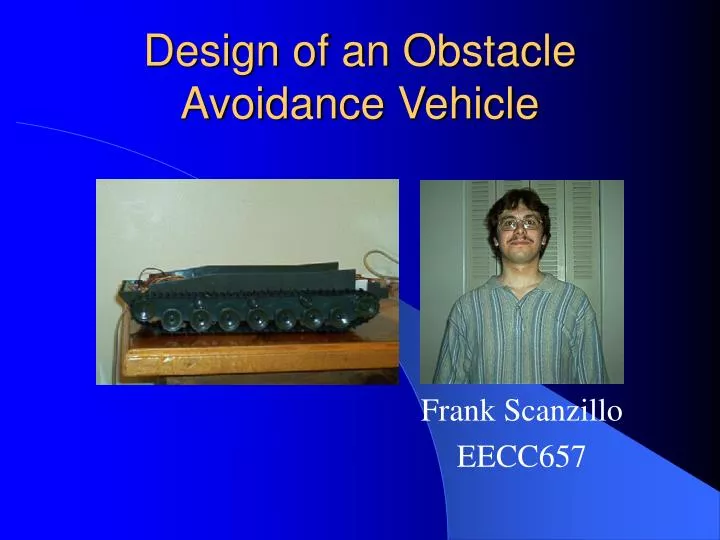
Design of an Obstacle Avoidance Vehicle Frank Scanzillo EECC657
Objectives • Detection and avoidance of obstacles • Detection of and navigation toward light beacon (final destination of vehicle)
Specifications • Maximum distance from tank to beacon: 7.8 m • Accuracy of destination: 25 cm radius • Minimum dimensions of obstacles: 23.5 x 23.5 cm, height 9 cm • Maximum height of obstacles: 20 cm • Minimum height of beacon emitter/detector: 25 cm • No objects within 3 cm of vehicle prior to system power-up Photo light detector IR beacon (target) 18 cm Light detector stand Infrared object sensors Optoreflector Tank 25 cm Obstacle 7 cm 1 cm
User Interface • Power on/off • LED status lights • Normal operation • Target reached • Vehicle stuck On L2 Failure L1 Success L0 Normal Off Power Switch Status Lights
Microcontroller Interfaces Microcontroller Port AD Port A Port B Opto L2 FL FR ML1 MR1 Photo L1 LSF RSF L0 LSR RSR ML0 MR0 RL RR Status light outputs DC motor inputs Sensor outputs System block diagram
Analytical Component • Required type, number, and configuration of sensors • Calculation of sensing distances • Stopping distance • Effective turning radius • Sensor body dimensions/beam widths • Calculation of object size limits • Algorithm for system (flowchart)
Sensors Used • Sharp GP2Y0A21YK (4) • Sharp GP2Y0D340K (4) • Panasonic PNA4602M 38 kHz IR Photodetector • Optek OPB745 Optoreflector
Sensor Configuration W Infrared object proximity sensors DFH SFH2 Photo light detector Infrared sensor beams SF2 SF1 ½ L SS2 SS1 SSV2 L DSH SSV1 DSV DFV SFV1 SFV2 SSH2 SSH1 ½ W WO SFH1
Sensor Configuration (cont.) R2 = 90 W
Calculation of Sensing Distances (front/rear) • Stopping distance: dS = 1.3 + 0.5 cm • Virtual turning radius: zero • Effective turning radius: d = 40.97 cm t = 1.74 cm • Sensor body dimensions: GP2Y0A21YK: 4.46 x 1.35 cm SFV1’ = t + dS + DFV + EFV1 + ESFV1 = 1.74 + 1.3 + 1.16 + 1.71 + 1 SFV1’ = 6.91 + 1.00 cm • Beam width: SF2> 28.8 cm (upper bound) SF1< 7.35 cm (lower bound)
Calculation of Sensing Distances (side) Sensor body dimensions: GP2Y0D340K: 1.5 x 0.9 cm Distance of beam vertex from vehicle: 1.5 + 0.5 cm W Infrared object proximity sensors DFH SFH2 Photo light detector Infrared sensor beams SF2 DSH = 0.39 + 0.39 cm SSH1 = dSS + DSH + EDSH = 1.5 + 0.39 + 0.39 SSH1 = 2.28 + 1.00 cm DSV = 8.0 + 0.5 cm SSV2 = L - DSV + ESV + ESSV2 = 37.5 – 8 + (0.2 + 0.5) + 1 SSV2 = 31.2 + 2.0 cm SF1 ½ L SS2 SS1 SSV2 L DSH SSV1 DSV DFV SFV1 SFV2 SSH2 SSH1 ½ W WO SS2> 34.7 cm (upper bound) SFH1 SS1< 10.23 cm (lower bound)
Object size limits Infrared object proximity sensors DFH W SFH2 Photo light detector Infrared sensor beams SF2 SF1 ½ L SS2 SS1 SSV2 L WO = 23.5 cm (minimum width of each obstacle) DSH SSV1 DSV DFV SFV1 SFV2 SSH2 SSH1 ½ W WO SFH1
Finalized proposal Obtained/purchased tank, logic gates, LEDs, some sensors and batteries Modified tank chassis Eliminated excess wiring Tested DC motor inputs/outputs Obtain voltage regulators, NiMH batteries/charger, HC12 board, a few more sensors Set up and test voltage regulators Set up, align, and test sensors Develop device drivers and test all interfaces System level coding, testing and verification Prepare final report/demo Current Status
Test Plan • Voltage regulators • Verify that supply voltage for motors/sensors and beacon = 5 + 0.25 V • Voltage regulator output (adjustable) for microcontroller = 5.3 + 0.2 V • Object sensors • Position small object (i.e. < 1 cm wide) 5.94 + 0.20 cm from front/rear of vehicle, aligned with the center of the front/rear bumper; verify that output > 2V for both front/rear sensors, and that voltages are equal. • Position either side of vehicle directly next to wall; verify that output > 1.2 V from closest front/rear sensor. • Follow similar procedure to verify alignment and range of side proximity sensors. • DC motors: Write code to sample all five legal functions of motors (i.e. forward, reverse, turn left/right, stop), for 2 seconds each, ensuring that the vehicle moves as instructed. The vehicle should move in a straight line forward or backward, and have no virtual turning radius. • Beacon/photodetector: Verify that the frequency of oscillation is 38 + 2 kHz, and that the photodetector can sense the beacon up to 8 meters away. • Optoreflector: Verify that a “good” logic high (> 4.3 V) is produced when a reflective strip is 1 cm from the lens, and that a “good” low (< 0.8 V) is produced when there is no reflective strip present. Write some code to test the output of the optoreflector and verify that the correct binary values are stored.
Test plan (cont.) System level test cases: • Place vehicle in a closed room with several obstacles scattered, and the beacon placed at the far end of the room. Turn the vehicle so that the photodetector is facing the direction opposite the beacon and turn the power on. Verify that the tank reaches its target before powering down. • Surround the vehicle with obstacles in an enclosed area. Place the beacon outside the enclosed area and verify that the “stuck” status light is triggered.
Power Consumption M68HC12: 350 mW expanded mode DC motors: (500 mA)(5V) = 2.5W each Object sensors: (40 mA)(5V) = 200 mW each Beacon (555 Timer): (5V)(15mA) = 75 mW Optoreflector: 100 mW LED + 100 mW photodarlington IR Photodetector: 200 mW Total power dissipation: 0.35 + 2(2.5) + 0.2(8) + 0.075 + 0.2 + 0.2 = 7.425 W