Download

1 / 41
410 likes | 501 Views
Using Registers. Ch.7 – p.158 Topic 1. Base - Displacement. PACK PDEC(3),ZDEC(3). See page 159. Displacement Memory address distance from the most recent USING Length Number of bytes Base Register Established by BALR & USING. A program address is base + displacement.

E N D
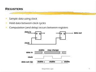
Using Registers Ch.7 – p.158 Topic 1
Base - Displacement PACK PDEC(3),ZDEC(3) See page 159
Displacement Memory address distance from the most recent USING Length Number of bytesBase Register Established by BALR & USING. A program address is base + displacement Base - Displacement
Add (Binary) Instruction Example: A REG,ONHND(IXREG)
Add Instruction Family (A, AR, AH) • The second operand is added to the first operand, and the sum in placed at the first-operand location. The operands and the sum are treated as 32-bit (for AH, second operand is treated as 16-bit) signed binary integers. • When there is an overflow, the result is obtained by allowing any carry into the sign-bit position and ignoring any carry out of the sign-bit position, and condition code 3 is set. If the fixed-point-overflow mask is one, a program interrupt for fixed-point overflow occurs. • 0 no overflow1 result < 0, no overflow2 result > 0, no overflow3 overflow
Subtract Instruction Example: S REG,ONORD(IREG)
Subtract Instruction Family (S, SR, SH) • The second operand is subtracted from the first operand, and the difference is placed at the first-operand location. The operands and the difference are treated as 32-bit (SH, 2nd operand is treated as 16-bit) signed-binary integers. • When there is an overflow, the result is obtained by allowing any carry into the sign-bit position and ignoring any carry out of the sign-bit position, and condition code 3 is set. If the fixed-point-overflow mask is one, a program interruption for fixed-point overflow occurs. • 0 result 0, no overflow1 result < 0, no overflow2 result > 0, no overflow3 overflow
Multiply Instruction Family (M, MR, MH) • The second word of the first operand (multiplicand) is multiplied by the second operand (multiplier), and the double-word product is placed at the first operand location. For M, the R1 field designates a even-odd pair of GPRs and must designate an even-numbered register, otherwise a specification exception is recognized. • Both multiplicand and multiplier are treated as 32-bit (for MH, multiplier is treated as 16-bit) signed binary integers. • No condition codes are set. MR 4,9 4 PRODUCT 5 MULTIPLICAND PRODUCT 9 MULTIPLIER
DIVIDE Instruction Family (D, DR) • The double-word first operand (dividend) is divided by the second operand (divisor), and the remainder and the quotient are placed at the first operand location. • The R1 field designates an even-odd pair of GPRs and must designate an even-numbered register, otherwise a specification exception is recognized. • The dividend is treated as a 64-bit signed binary integer, The divisor, the remainder, and the quotient are treated as 32-bit signed binary integers. The remainder is placed in R1 and the quotient is placed in R1+1. DR 6,9 6 REMAINDER 7 QUOTIENT 9 DIVISOR
COMPARE Instruction Family (C, CR, CH) • The first operand is compared with the second operand, and the result is indicated in the condition code. • The operands are treated as 32-bit signed binary integers • 0 operands are equal1 first operand is low2 first operand is high3 - - - - CR 5,8 C WEEK-HRS,40HRS
BRANCH ON COUNT Instruction family (BCT, BCTR) • One is subtracted from the first operand, and the result is placed at the first-operand location. The first operand and result are treated as 32-bit binary integers with overflow ignored. When the result is zero, normal instruction execution sequencing proceeds with the updated instruction address. When the result is not zero, the instruction address in the current PSW is replaced by the branch address (the second operand). • In the 2-byte format, if R2 operand is zero, no branch is taken, however one is still subtracted from R1 • The condition code is not used. BCT 3,LOOP
CONVERT TO BINARY • Converts a Packed Decimal number to Binary • Result is stored in the register (first operand) • 2nd operand (B2,D2) must be 8 bytes
CVB • CVB R1,D2(X2,B2) • CVB 7,PDECIMAL • --- • PDECIMAL DC XL8’000000000000256F’
CONVERT TO DECIMAL • Reverse of Convert to Binary • Converts binary value in a register to packed decimal format and stores it in 8 bytes
CVD • CVD R1,(D2(X2,B2) • L 6,HUNDRED • CVD 6,BINVALU • - - - - • BINVALU DS PL8 • HUNDRED DC F’256’ *00 00 01 00
NUM is a 2-byte field with a value between 01 and 10. It is read in from an input file. It is used to index into a table with 10 different hourly salaries and NUM is consistent with the salary code number from a time-card. NUM must be in binary format to be used as an index. Reg 7 contains the address on memory of the pay rate table (not shown) and each entry in the table is 5-bytes. The paycode is read in, PACKed and converted to binary. The appropriate table entry corresponding to the code is accessed and the pay rate is outputted to the monitor with a WTO instruction.
COMPARE LOGICAL • Compare Logical Characters (CLC) • 6-byte instruction format (SS) • CLC D1(L,B1),D2(B2) • Compare up to 256 characters • Compare Logical Immediate (CLI) • 4-byte instruction format (SI) • CLI D1(B1),I2 • Compare a single byte
CLC, CLI • Different than arithmetic compare instructions – all characters are unsigned • CLI compares a single byte in memory with a single byte that is included with the instruction (I2 field) • CLC compares a byte at a time left-to-right (low-to-high) • Both Compare instructions set the condition code
CLC, CLI • Condition Code: • 0 operands are equal1 first operand low2 first operand high3 - - - CLI AB+10,C’C’ AB D1 D6 C8 D5 E2 D6 D5 6B C1 4B C2 4B AC D1 D6 C8 D5 E2 D6 D5 6B C1 4B C3 4B What is the CC that is set? ____________ 1
MOVE Instructions • Move Characters (MVC) • Move Immediate (MVI) • Move Numerics (MVN) • Move Zones (MVZ) • Second operand is placed at the first operand location – left-to-right
Move Characters (MVC) • MVC D1(L,B1),D2(B2) • Move up to 256 bytes from 2nd operand to the 1st operand • Examples: • MVC OUTAREA(80),INAREA • MVC OUTPRICE(5),UNITCOST
Move Immediate (MVI) • MVI D1(B1),I2 • Moves a single character from the 2nd operand to the 1st operand • 2nd operand is data within the instruction • MVI OUTPRICE+0,c’$’
Move Numerics (MVN) • Generally, used with zoned-decimal data – moves only the numeric part of the byte (not the zones) FLDA C6 C7 C8 C9 F0 F1 F2 F3 F4 F5 FLDB MVN FLDB(4),FLDA FLDA C6 C7 C8 C9 FLDB F6 F7 F8 F9 F4 F5
Move Zones (MVZ) • Generally, used with zoned-decimal data – moves only the zones part of the byte (not the numerics) FLDA C6 C7 C8 C9 F0 F1 F2 F3 F4 F5 FLDB MVZ FLDB(4),FLDA FLDA C6 C7 C8 C9 FLDB C0 C1 C2 C3 F4 F5
Defining Binary Data • Page 162 in your textbook • Examples: FW DC F’1’ * 00 00 00 01 *HW DC H’123’ * 00 78 *FWN DC F’-123’ * FF FF FE DD*DW DS DFW4 DS 4FHW3 DS 3H
Defining Address Constants DCBADD DC A(INDCB)INBUFADD DC A(INBUFFER) INDCB INDCB INBUFFER INBUFFER
Multiple Instructions • Load Multiple (LM) • Store Multiple (STM)
READING ASSIGNMENT • Read Ch.7 – Topic 1 • But, you do not need to read the section called “Some System/370 Instructions” beginning on page 170 through the end of the Topic – page 175. • But you can read the section if you want.
More About Binary Arithmetic Ch.7 Topic 2 Page 176
Working with Negative Numbers • Let’s say you have a numeric value in a register, but you don’t know if it’s positive or negative. How can you tell? • Is the number in the register above positive or negative? _______________ • How can you tell? _____________________________________ 80 00 00 33 negative High-order bit is set to one.
How Can You Tell? • Registers are 32 bits in length • 31 bits are used to represent values • High-order (left-most) bit is used to identify the sign • Bit is “1” represents a negative value • Number is in 2’s complement format (2’s complement format essentially is the bits are flipped – 1 bits become 0 and 0 bits become 1
How Does It Work? FF FF FE DD • High-order bit is “1” – value is negative • Flip all the bits from 1 to 0 or from 0 to 1 • Then add 1 • Result is negative 123 00 00 01 22 00 00 01 23
Can You Convert the Other Way? • To convert a positive binary value: • Subtract 1 from the original value • Flip all the bits = 00 00 01 23 FF FF FE DD 0000 0001 0010 0011 1111 1110 1101 1101 0000 0001 0010 0010 - 1
So How Do I Test the High-Order Bit? • If the value is in memory, use TM • Test Under Mask instruction • 4-byte format (SI)
Test Under Mask (TM) • TM examines selected bits of a byte and sets the condition code • 0 selected bits are all zeros1 selected bits mixed zeros & ones2 - - -3 selected bits are all ones • What bits are examined?The 1-bits in the Mask field TM VALUE,X’C1’ MASK= 1100 0001 BZ BITSOFF ALL BITS OFF BO BITSON ALL BITS ON BM BITSMIXD BITS ON AND OFF : VALUE DC XL4’E7B3C1F2’ Which branch is taken? _________________________ BITSON
Binary Arithmetic Assignment • Using your Carlton Realtors program, change the decimal arithmetic to binary arithmetic accomplishing the same as you did using decimal arithmetic. • Due: next week