Download
1 / 56
560 likes | 751 Views
Commissioning EMMA. the World's First Non-Scaling FFAG Accelerator. Susan Smith STFC, ASTeC. Contents. Contents. Introduction What are ns-FFAGs? and Why EMMA? The international collaboration EMMA goals and requirements Layout and Lattice Injection & Extraction Diagnostics

E N D
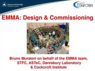
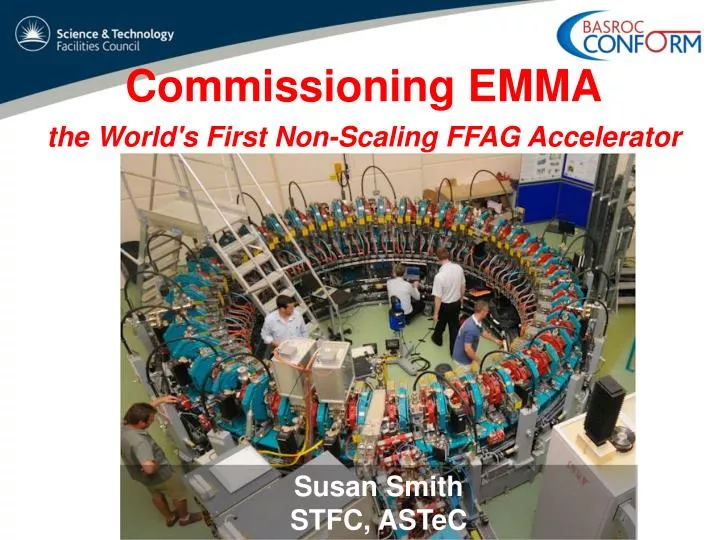
Commissioning EMMA the World's First Non-Scaling FFAG Accelerator Susan Smith STFC, ASTeC
Contents • Introduction • What are ns-FFAGs? and Why EMMA? • The international collaboration • EMMA goals and requirements • Layout and Lattice • Injection & Extraction • Diagnostics • Radiofrequency • Beam Commissioning • Next Steps • Schedule • Summary
Project Overview BASROC(The British Accelerator Science and Radiation Oncology Consortium, BASROC) • CONFORM project ( COnstruction of a Non-scaling FFAG for Oncology, Research, and Medicine ) • 4 year project April 2007 – March 2011 • 3 parts to the project • EMMA design and construction~ £6.5m (~$9M) Electron Model for Many Applications (EMMA) • PAMELA design study • Applications study
Applications of ns-FFAGs • Proton & Carbon Therapy • Neutrino Factory High power proton driver • Sub-critical Thorium Reactor • Dedicated Muon Source
Non-scaling FFAG Novel, unproven concepts which need testing Electron Model => EMMA! • Born from considerations of very fast muon acceleration • Breaks the scaling requirement • More compact orbits ~ X 10 reduction in magnet aperture • Betatron tunes vary with acceleration (resonance crossing) • Parabolic variation of time of flight with energy • Factor of 2 acceleration with constant RF frequency • Serpentine acceleration • Can mitigate the effects of resonance crossing by:- • Fast Acceleration ~15 turns • Linear magnets (avoids driving strong high order resonances) • Or nonlinear magnets (avoids crossing resonances) • Highly periodic, symmetrical machine (many identical cells) • Tight tolerances on magnet errors dG/G <2x10⁻⁴
Muon Acceleration Model • EMMA was originally conceived as a model of a 10-20 GeV muon accelerator • Designed to demonstrate that linear non-scaling optics work and to make a detailed study of the novel features of this type of machine • Variable tunes with acceleration • Parabolic variation of time of flight with energy • - Serpentine acceleration
EMMA International Collaboration • EMMA design is an international effort and we recognise and appreciate the active collaboration from: • Brookhaven National Laboratory • Cockcroft Institute UK • Fermi National Accelerator Laboratory • John Adams Institute UK • LPSC, Grenoble • Science & Technology Facilities Council UK • TRIUMF • ………..
EMMA Goals Graphs courtesy of Scott Berg BNL
Understanding the NS-FFAG beam dynamics as function of lattice tuning & RF parameters Lattice Configurations Tune plane • Example: retune lattice to vary resonances crossed during acceleration Time of Flight vs Energy • Example: retune lattice to vary longitudinal Time of Flight curve, range and minimum Graphs courtesy of Scott Berg BNL
Accelerator Requirements • Injection & extraction at all energies, 10 - 20 MeV • Fixed energy operation to map closed orbits and tunes vs momentum • Many lattice configurations • Vary ratio of dipole to quadrupole fields • Vary frequency, amplitude and phase of RF cavities • Map longitudinal and transverse acceptances with probe beam EMMA to be heavily instrumented with beam diagnostics
ALICE Accelerators and Lasers In Combined Experiments Parameter Value Nominal Gun Energy 350 keV Injector Energy 8.35 MeV Max. Energy 35 MeV Linac RF Frequency 1.3 GHz Max Bunch Charge 80 pC Emittance 5-15 mm-mrad EMMA
EMMA Parameters & Layout Diagnostics Beamline Injection Line
EMMA Ring Cell 65 mm Field Clamps 55 mm D D F Low Energy Beam • 42 identical doublets Cavity Beam stay clear aperture High Energy Beam 110 mm Magnet Centre-lines 210 mm Independent slides
EMMA Cell FQUAD Cavity DQUAD Ion Pump Ion Pump Ion Pump Beam direction Girder
A 6 Cell Girder Assembly F Magnet Location for diagnostics Cavity D Magnet Ion Pump Girder Beam direction
Injection & Extraction • Large angle for injection (65°) and extraction (70°) very challenging !! • Injection/Extraction scheme required for all energies (10 – 20 MeV) • Many lattices and many configurations of each lattice required • Very limited space between quadrupole clamp plates for the septum and kickers construction Extensive 3D magnet modelling conducted to minimise the effect of stray septum fields on circulating beam Injection Septum 65° Kicker Kicker
Injection Region Injection Septum 65° Kicker Kicker
Injection Septum Kicker Kicker Septum Power supply
Septum Design Translation Rotation Septum out of vacuum chamber • Inject/Extracts from 10-20 MeV • For all lattice configurations Section view of septum in vacuum chamber
Kicker Magnet, Fast Switching Kicker Magnet Power Supply parameters With compact design and require: • Fast rise / fall times 35 nS • Rapid changes in current 50kA/S • Constraints on pre and post pulses Prototype R&D led to a contract with APP for production units
Measured Current Pulsesfrom Kicker Magnet ~55.5 ns = 1 revolution period
EMMA Ring Wall Current Monitor Septum Power Supply Kicker Power Supplies YAG Screen YAGScreen Septum Power Supply Kicker Power Supplies eBPM x 81
Electron Beam Position Monitors Coupler CST 2D Map Detector card • 50 mm resolution over a large aperture • Locally mounted coupler cards • Amplifies signals from opposite buttons, coupler and strip line delay cables provides two pulses with ¼ rev. period delay on same cable • VME Detector card in rack room outside of shielded area digitised
Vacuum chamber & BPM 4 x BPM bodies, accurately machined and welded into vacuum chamber • Standard vacuum chambers each covering 2 cells BPM Bellows BPM BPM Ø48 mm ± 25m r.m.s. resolution required FQ DQ BPM block cross-section showing pickups
RF Requirements • Voltage: • 20 - 120 kV/cavity essential, based on 19 cavities • Frequency: • 1.3 GHz, compact and matches the ALICE RF system • Range requirement 5.6 MHz • Cavity phase: • Remote and individual control of the cavity phases is essential
RF System Overview LLRF RF Cavities High Power RF Amplifier System Waveguide Distribution System
Cavity Design & Specification Aperture Ø 40 mm 2.0 90 • 20 cavities delivered by Niowave • Q0 typically > 19000
RF Source • A single 100kW (pulsed) IOT supplying the 19 RF cavities distributed around EMMA • VIL409 high power RF amplifier system in 3 racks • Tested to ensure required bandwidth • Delivery was completed in July 2009 • Thorough software and system tests completed at Daresbury in September 2009 CPI 100 kW (pulsed) IOT
RF Distribution • Acceptance tests demonstrated: • 196 ° of phase shift achievable for each RF distribution, with a resolution of 0.1° • <0.2 dB variation measured over operating frequency • Isolation tests between ports showed better than 42 dB (typically 50 dB) • measurements of the forward and reverse directional couplers showed a coupler directivity of greater than 41 dB (specification >40 dB). Distribution system developed by Q-Par Angus (UK).
EMMA LLRF • Instrumentation Technologies Libera LLRF system provides • Initial cavity setting conditions • Control of the cavity amplitude and phase to ensure stable controls the acceleration • Diagnostic monitoring • Cavity pick-up loops • Forward and reverse power monitoring to each cavity • IOT power levels before and after the circulator • Novel synchronisation of the accelerators • A 200µs beam pre-trigger used to reset LLRF phase accumulators every beam pulse: • The LLRF synchronises itself on every trigger pulse, preserve the relationship between ALICE 1.3 GHz and EMMA offset frequ.
First high power commissioning Started17/8/10 • Excellent cavity control stability (up to 40 kW) • 0.007% rms voltage • 0.027o phase • Phase synchronisation with ALICE has not yet been demonstrated
Many thanks for the efforts of all the team. 4 Sector Commissioning screen screen
Complete Ring Second Turn First Turn 16th Aug 2010
Optimisation of injection Kicker Septum Kicker • Angle at end of SEPT determined from BPM offsets with quads OFF Use code to determine kicker strengths close to pragmatic strengths Orbit kinks between cells are due to rotation of coordinate system
Time of Flight Revolution time @ equiv 18.5 MeV/c, equivalent momentum = 55.3+/-0.1 ns Variable ALICE energy fixed EMMA fields Fixed ALICE Energy Variable EMMA fields • Time of flight is determined by path length, not by speed • Use different magnetic strength as easier than retuning ALICE injector • Raw signal of one BPM electrode for time of flight measurement ALICE injector
Betatron oscillation tunes & dispersion • Tunes from fit • Beam position at 7 BPMs • Dispersion from average position At 100% effective momentum (15.5 MeV/c) Horzdisp =82mm Vert. disp. = 3mm Consistent to predicted values Horizontal Vertical
Coasting beam no RF Without rf, beam circulates more than 1000 turns Left and right electrode signal of BPM spaced with 13 ns.
Next Steps • Commissioning now • LLRF system fully functional and tested at ALICE & off frequency • Verification of successful accelerator, inside/outside bucket • Characterisation • Tunes and ToF fn of E ~ 1MeV steps • Tune accelerator to match required lattice • “EMMA Experiment” • Acceleration 10 – 20 MeV • Resonance crossing • Detailed bench marking with codes • Scan aperture in phase space (both longitudinally and transversely) • Benchmark measured dynamic aperture with and without acceleration against the simulations ...................