Download
1 / 62
680 likes | 2.66k Views
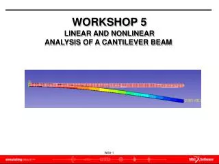
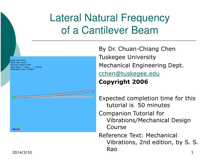
Lateral Natural Frequency of a Cantilever Beam. By Dr. Chuan-Chiang Chen Tuskegee University Mechanical Engineering Dept. cchen@tuskegee.edu Copyright 2006 Expected completion time for this tutorial is 50 minutes Companion Tutorial for Vibrations/Mechanical Design Course

E N D
Lateral Natural Frequencyof a Cantilever Beam By Dr. Chuan-Chiang Chen Tuskegee University Mechanical Engineering Dept. cchen@tuskegee.edu Copyright 2006 Expected completion time for this tutorial is 50 minutes Companion Tutorial for Vibrations/Mechanical Design Course Reference Text: Mechanical Vibrations, 2nd edition, by S. S. Rao
Table of Contents (TOC) • Educational Objectives • Problem Description • Suggested Steps • Step by Step Process • Viewing the Results of the FE Analysis • Analytical Analysis of a Cantilever Beam • Comparison of Analytical to Finite Element Analysis • Results of (Mode Shapes) • To use the TOC hyperlinks left click the entire topic then right click your mouse and open a hyperlink to the PowerPoint slide of interest.
Table of Contents • Summary and Discussion • Cantilever Beam Exercise • Appendix A: • Background of Finite Elements • Finite Element Theory • Finite Element Textbooks and Sources • Acknowledgement
Table of Contents • Practice Problem • Appendix A : • Background Information • Finite Element Theory • Finite Element Theory sources
Educational Objectives The educational goal is to provide undergraduate engineering students with understanding of a specific engineering topic and FE theory, along with an ability to apply commercial FE software to typical engineering problems. The educational goal will be accomplished through four educational objectives based upon Bloom’s Taxonomy and ABET Criteria 3 as follows: 1. Engineering Topics (Comprehension: 3a, 3k). Understand the fundamental basis of engineering topics through the use of finite element computer models.
Educational Objectives 2. FE Theory (Comprehension; 3a). Understand the fundamental basis of FE Theory. 3. FE Modeling Practice (Application; 3a, 3e, 3k). Be able to implement a suitable finite element model and construct a correct computer model using commercial FE software. 4. FE Solution Interpretation and Verification (Comprehension and Evaluation; 3a, 3e) Be able to interpret and evaluate finite element solution quality, including the importance of verification .
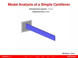
Problem Description • Analysis Objectives • Determine the natural frequencies and modes in a cantilever beam • Use the finite element method to determine the modes shapes at resonant frequencies
0.9”x0.9” 50 “ Problem DescriptionModel Definition • Cantilever beam (0.9”x0.9” cross section with a length of 50”) • Determine the natural frequencies • Plot the mode shapes
Overview of SolidWorks and COSMOSWorks • SolidWorks • SolidWorks is a parametric, solid, feature-based computer aided design (CAD) system. In SolidWorks, you sketch ideas and experiment with different designs to create 3D models. A SolidWorks model is made of : Parts, Assemblies or Drawings. • A part is a single 3D object made up of features. Features are the shapes and operations that construct the part. A part can become a component in an assembly, and it can be represented in a 2D drawing. • A assembly is a document in which parts, features and other assemblies ( sub-assemblies) are mated together.
Overview of SolidWorks and COSMOSWorks • COSMOSWorks • COSMOSWorks is finite element analysis software which is fully integrated with the solid modeling software SolidWorks. COSMOSWorks uses finite element analysis to simulate the working conditions of engineering designs and predict their behavior. Powered by fast solvers, COSMOSWorks makes it possible for designers to quickly check the integrity of their designs and search for optimum solutions. COSMOSWorks can perform static, thermal, buckling, frequency, compressible/incompressible fluid flow, drop test and optimization analysis of parts and assemblies.
Three-Dimensional Model Assumptions • In constructing the 3-dimensionional model of the beam, there are some assumptions that can be made to assure that the model is accurate • Assumptions • The material is isotropic and elastic
The Steps to Analyze a Cantilever Beam • A 3-dimensional model will be constructed using the SolidWorks CAD software and loads and restraints applied to this solid model. • The 3-dimensional model is then meshed in prior to using COSMOSWorks to perform a Finite Element Analysis of the model • Mode shapes with corresponding natural frequencies are produced
General Steps • Create a geometric model of the cantilever beam • Define the material properties • Define the boundary conditions • Create a finite element mesh of this model • Submit the model to COSMOSWorks for analysis • Post Process the results of analysis using COSMOSWorks • Compare this finite element results with the analytical analysis
Tutorial Step by Step Process • Overview of SolidWorks and COSMOSWorks • Left Side of SolidWorks/COSMOSWorks Window • Use of the SolidWorks Interface • Toolbars • Tutorials and Getting Help • Creating a SolidWorks Model of the beam • Setting the Drawing Units to Inches in SolidWorks • Creating a SolidWorks Model of the beam • Verify that COSMOSWorks is loaded in your Computer
Tutorial Step by Step Process • Opening your Model in COSMOSWorks • The COSMOSWorks Study Folders • Assigning Material Properties to the Model • Assigning Material Properties to the beam • Applying Restraints or Boundary Conditions to the beam • Meshing the Model and Running the Study
Tutorial Step by Step Process • Viewing the Results of the Finite Element Analysis • Viewing Natural Frequencies • Viewing Mode Shapes • Animation of Lateral Vibration of a Cantilever Beam • Analytical Analysis of a Cantilever Beam • Comparison of Results between Analytical and Finite Element Analysis • Summary and Discussion
Overview of the SolidWorks Window • Menu Bar • Sketch Toolbar/Sketch Relations Toolbar • Confirmation Corner with Sketch Indicator • Graphics area • Sketch Origin • Reference Triad
Left Side of SolidWorks/COSMOSWorks Window • Feature Manager icon • Feature Manager design tree • COSMOSWorks icon • COSMOSWorks Manager tree
Using the SolidWorks Interface • Toolbar area • Feature Manager window • Graphical Interface window
Toolbars • You can select which toolbars to display under View in the menu heading • Toolbars are moveable to top, and sides of the window • Icon Buttons for frequently used commands
Tutorials and Getting Help • Click the Help menu and choose either • COSMOSWorks Online Tutorials • SolidWorks Online Tutorials • Click the Help menu and choose Help Topics for either • COSMOSWORKS • SolidWorks
Creating SolidWorks Model of the Beam • 1.Create a new part. Click on the Standard toolbar. • The New SolidWorks Document dialog box appears • 2. Select the Part icon • 3.Click OK
Creating a SolidWorks Model of the Cantilever Beam • Create a Base Feature (Rectangle) of the beam by Boss Extrusion on the Front Plane • First left click on the Sketch Icon
Creating a SolidWorks Model of the Cantilever Beam • Open the SolidWorks sketch on the Front Plane. • Left click on the Front Plane Icon.
Setting the Drawing Units to Inches in SolidWorks • Setting the Drawing Units • 1. Left click on the Tools menu and select Options • 2. SelectDocument Properties in the Systems Operations Menu. • 3. Under Document Properties select Units. • 4. Choose inches in both locations inside your Document Properties • 5.Click Ok to close menu
Creating a SolidWorks Model of the Cantilever Beam • 1. Left click on the Rectangle Icon and create a rectangle • 2. Left click on theCenterline Icon and then left click the two points in diagonal direction. • Click OK after diagonal centerline appears
Creating a SolidWorks Model of the Cantilever Beam • 3.Left click on the Add Relation Icon and select the centerline and origin • Left click Midpoint and then left Click OK to move the center of rectangle to the origin
Creating a SolidWorks Model of the Cantilever Beam • 5. Left click on the Smart Dimension Icon and dimension the width of the rectangle to be 0.9” • 6. Dimension the height of the rectangle to be 0.9”, • Left click OK to close the dimension dialog box on the left
Creating a SolidWorks Model of the Cantilever Beam • 7. Left click the Extruded Boss/Base Icon and the sketch will be extruded into a 3-D solid. • 10. Select direction 1 to be Blind and d1 to be 50 in. • 11. Finally click the green OK button to complete the rectangular beam.
Creating a SolidWorks Model of the Cantilever Beam • Click zoom to fit . This is what your beam will look like as a 3D solidWorks model. • Finally prior to opening your model inside, COSMOSWorks, Save it to your computer directory. • Give the model a name that you can remember and SAVE it. The file has an extension name is .prt ) • (Vibration Tutorial 1.prt).
Verifying that COSMOSWorks is loaded on your computer • 1. Click the Tools item on the menu and select Add-Ins. • 2. The Add-Ins box should appear and verify that the COSMOSWorks 2007 box is checked.
Opening your Model in COSMOSWorks • 1. Click the COSMOSWorks Analysis Manager tab • 2. In the COSMOSWorks Manager tree right click the Vibration Tutorial 1 and select Study • 3. The Study dialog box appears
Opening your Model in COSMOSWorks • 4. In the Study dialog box type in a name for study:Cantilever Beam and select Solid Mesh. • 5. Under Type of study select Frequency. • 6. Click theOK check when done • 7. To specify the range of frequency, right click Cantilever Beam, and select Properties • 8.A Frequency window will pop up, choose 5 for the Number of frequencies
The COSMOSWorks Study Folders • COSMOSWorks automatically creates a folder called Cantilever Beam with the following sub folders: Solids, Load/Restraint, Design Scenario, Contac/Gaps, Mesh and Report folders • We are now ready to define the mathematical model. This process generally consists of the following steps: • Geometry preparation • Material properties assignment • Restraints application • Contract/Gap assignment • Load application • The Contact/Gaps Icon will not be used in this Tutorial
Assigning Material Properties to the Model • We now have a 3D model of the beam and need to assign material properties to it. • We will select AISI 1020 Steel as the material for this model. • COSMOSWorks will then assign the material properties of AISI 1020 Steel to the beam.
Assigning Material Properties • 1. Right click the Solids Icon and select Apply Materials to All Bodies • 2. Once the Material dialog box appears for Sourceselect fromLibrary Files. • 3.Select the AISI 1020 Steel from the list of materials. • 4.Click OK
Applying Restraints or Boundary Conditions to the Beam • 1. In the COSMOS Tree Right click the Loads/Restraints Icon and select Restraints. • 2.In the Restraints dialog under Type select Fixed • 3. Left click inside the dialog box then select the front face of the beam model.
Applying Restraints or Boundary Conditions • 4. The Restraints dialog box will contain Face<1> and the Top Surface of the Beam Model will have restraints symbols on it. • 5. Now left click to close.
Applying Restraints or Boundary Conditions • To keep the beam in y-z plane, let’s keep the displacement in the x-direction on the right face to be zero • 1. In the COSMOS Tree Right click the Loads/Restraints Icon and select Restraints. • 2.In the Restraints dialog under Type selectOn flat face. • 3. Left click inside the dialog box, then select the right face of the beam. • 4. Under Translation, left click the third icon (Normal to face) and make the translation 0 • 5. The Restraints dialog box will contain Face<1> and the Right Surface of the beam will have restraints symbols on it. • 6. Now left click the check symbol to close.
Meshing the Model and Running the Study • 1. In the COSMOSWorks Manager tree, right click the Mesh Icon and select Create Mesh. • 2.The Mesh Parameters Manager will appear, check the Run box and left click the Options (Run analysis after meshing) box. • 3. Expand Options and a larger window appears: • Mesh Quality-High • Mesh Control- Smooth Surface • Jacobian Check-4 point • Mesher Type-Standard • Finally Click • 4. Click the green in the Mesh dialog box. Now, COSMOSWorks is performing analysis.
Viewing the Results of Finite Element Analysis • After the analysis, all the results will be shown in Results folder, expand the folder in tree, 5 Displacements and 5 Deformations will appear. • Double click on this Displacement 1Icon to view • Natural Frequency and deformation scale are shown on the left top corner in the graphical window
Viewing the Results of Finite Element Analysis • Folder plots can be edited by right clicking on the Plot and making a selection from : • Edit Definition • Animate • Section Clipping • Iso Clipping • Chart Option • Setting • Axes • Probe • List Selected • Print • Save as • Add to New Folder • Copy • Delete
Natural Frequenciesby Finite Element Analysis • Right click the Results folder and select List Resonant Frequency to view the first five natural frequencies of the transverse motion, • A ‘List Modes’ window listing the frequencies will appear
Viewing Mode Shapes at Natural Frequencies • Double click the Deformation1, the mode shape at the first natural frequency appears. • Right click the mouse in the graphic window, and select View Orientation and *Right to get a better view the mode shape in y-z plane
Animation of Lateral Motion at • Right click the Displacement1, and select animate, an Animation dialog Box will appear (The Displacement1 needs to be in Bold font. If not, right click and select show) • Left click the play Icon, a motion animation will be played. • The playing speed can be also changed by adjusted the bar
y W(x, t): Deflection : Mass Density A: Cross Sectional Area L: length E: Young Modulus I: Second Moment of Inertia x Analytical Analysis of a cantilever beam • Expectations The analytical solution for the cantilever beam is readily available in the text “Mechanical Vibration” by Rao, page 394, 2nd Edition, 1990. The neutral frequencies are found from eqn (8.93) and Figure 8.15.
Comparison of Results between Analytical to Finite Element Analysis The natural Frequency can be found by plugging the numerical values into the equation. =0.2875 lb/in3 A=0.81 in2 L=50” E=30x106 psi I=0.05468 in4
Summary and Discussion The FEA can provide insight in determining the natural frequency and mode shapes of a uniform cross sectional cantilever beam. The FEA method provides another analysis tool for the engineer to develop reliable designs that can avoid the severe vibrations due to the excitation close to the resonant frequency.
Appendix A: • Background Information on Finite Elements • Finite Element Theory
Background Information • The purpose of this tutorial is to provide an introduction into using the finite element method* of engineering analysis and to gain experience using a commercial (FEA) software to analyze a structural problem with static loads. Finite element analysis, commonly called FEA is a numerical analysis method. FEA is a numerical analysis method used for solving field problems described by a set of partial differential equations. Other numerical methods include the Finite Difference Method, the Boundary Element Method, or the Finite Volume Method to name a few. COSMOSWorks is a commercial FEA software code capable of solving problems commonly found in design engineering. COSMOSWorks was developed by Structural Research & Analysis Corporation and has since merged with SolidWorks Corporation and both are currently owned by Dassault Systems. • * The use of the finite element method of analysis is rarely used for basic design work, because the factor of safety doesn’t justify the higher precision.