Download

1 / 31
400 likes | 751 Views
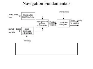
Fundamentals of Navigation Systems. Uğur Doğan GÜL. Outline. Coordinate Frames Earth-Centered Inertial Frame Earth-Centered Earth-Fixed Frame Local Navigation Frame Body -Fixed Frame Kinematics Attitude Angular Rate Cartesian Position Velocity Acceleration

E N D
Fundamentals of Navigation Systems Uğur Doğan GÜL
Outline • Coordinate Frames • Earth-Centered Inertial Frame • Earth-Centered Earth-Fixed Frame • Local Navigation Frame • Body-Fixed Frame • Kinematics • Attitude • Angular Rate • Cartesian Position • Velocity • Acceleration • Earth Surface and Gravity Models • The Ellipsoid Model of the Earth’s Surface • Curvilinear Position • Earth Rotation • Specific Force, Gravitation, and Gravity • Frame Transformations • Inertial and Earth Frames • Earth and Local Navigation Frames • Inertial and Local Navigation Frames • Transposition of Navigation Solutions
Coordinate Frames Earth-Centered Inertial Frame • Denoted by the symbol i, • Centered at the Earth’s center of mass, • Oriented with respect to the Earth’s spin axis and the stars,
Coordinate Frames Earth-Centered Inertial Frame • The z-axis always points along the Earth’s axis of rotation from the center to the North Pole (true, not magnetic), • The x-and y-axes lie within the equatorial plane, • They do not rotate with the Earth, but the y-axis always lies 90 degrees ahead of the x-axis in the direction of rotation.
Coordinate Frames Earth-Centered Earth-Fixed Frame • Denoted by the symbol e. • Similar to the ECI frame, except that all axes remain fixed with respect to the Earth. • The z-axis always points along the Earth’s axis of rotation from the center to the North Pole(true, not magnetic).
Coordinate Frames Earth-Centered Earth-Fixed Frame • The x-axis points from the center to the intersection of the equator with the IERS reference meridian (IRM), or conventional zero meridian (CZM), which defines 0 degree longitude. • The y-axis completes the right-handed orthogonal set, pointing from the center to the intersection of the equator with the 90deg east meridian. • The Earth frame is important in navigation because it is wanted to know the position relative to the Earth, so it is commonly used as both a reference frame and a resolving frame.
Coordinate Frames Local Navigation Frame • Denoted by the symbol n, • It’s origin is the point a navigation solution is sought for. • The z-axis, also known as the down (D) axis, is defined as the normal to the surface of the reference ellipsoid, pointing roughly toward the center of the Earth. • The x-axis, or north (N) axis, is the projection in the plane orthogonal to the z-axis of the line from the user to the North Pole. • By completing the orthogonal set, the y-axis always points east and is hence known as the east (E) axis.
Coordinate Frames Local Navigation Frame • The local navigation frame is important in navigation because it is wanted to know the attitude relative to the north, east, and down directions. For position and velocity, it provides a convenient set of resolving axes, but is not used as a reference frame.
Coordinate Frames Body-Fixed Frame • Denoted by the symbol b, • Comprises the origin and orientation of the object for which a navigation solution is sought. • The origin is coincident with that of the local navigation frame, but the axes remain fixed with respect to the body and are generally defined as x=forward, z=down, y=right, completing the orthogonal set.
Coordinate Frames Body-Fixed Frame • For angular motion, the x-axis is the roll axis, the y-axis is the pitch axis, and the z-axis is the yaw axis. Hence, the axes of the body frame are sometimes known as roll, pitch, and yaw. • The body frame is essential in navigation because it describes the object that is navigating. All strap down inertial sensors measure the motion of the body frame (with respect to a generic inertial frame).
Kinematics In navigation, the linear and angular motion of one coordinate frame must be described with respect to another. Most kinematic quantities, such as position, velocity, acceleration, and angular rate, involve three coordinate frames: • The frame whose motion is described, known as the object frame, α; • The frame with which that motion is respect to, known as the reference frame, β; • The set of axes in which that motion is represented, known as the resolving frame, γ. To describe these quantities the following notation is used for Cartesian position, velocity, acceleration, and angular rate: Where the vector, x, describes a kinematic property of frame α with respect to frame β, expressed in the frame γ axes. For attitude, only the object frame, α, and reference frame, β, are involved; there is no resolving frame.
Kinematics Euler Attitude Representation • In Euler attitude representation, the attitude is broken down into three successive rotations, namely yaw (), pitch (), and roll () rotation. • The Euler rotation from frame β to frame α may be denoted by the vector • Where the Euler angles are listed in the reverse order to that in which they are applied.
Kinematics Coordinate Transformation Matrix Representation The coordinate transformation matrix is a 3x3 matrix, denoted by . Coordinate transformation matrix can be used: • To transform a vector from one set of resolving axes to another (the lower index represents the “from” coordinate frame,α, and the upper index represents the “to” frame,β). • To represent the attitude (the lower index represents the object frame,α, and the upper index represents the reference frame,β). A set of Euler angles is converted to a coordinate transformation matrix by first representing the roll, pitch and yaw rotations as a matrix and then multiplying, noting that with matrices the order of the operation is important and, the first operation is placed on the right. Here ZYX order is used.
Kinematics Coordinate Transformation Matrix
Kinematics Why to use coordinate transformation matrix representation instead of Euler attitude representation? • Rotation cannot be reversed simply by reversing the sign of the Euler angles: However transpose of the coordinate transformation matrix is used to reverse the rotation: • Successive rotations cannot be expressed simply by adding the Euler angles: However to perform successive rotations coordinate transformation matrices are simply multiplied:
Kinematics Angular Rate The angular rate vector,, is the rate of rotation of the α-frame axes with respect to the β-frame axes, resolved about the γ-frame axes. The angular rate tensor is the skew-symmetric matrix of the angular rate vector: It can be shown, using the small angle approximation applied in the limit δt→0, that the time derivative of the coordinate transformation matrix is:
Kinematics Cartesian Position The Cartesian position of the origin of frame α with respect to the origin of frame β, resolved about the axes of frame γ, is: where x, y, and z are the components of position in the x, y, and z axes of the γ frame. Position may be resolved in a different frame by applying a coordinate transformation matrix:
Kinematics Velocity Velocity is defined as the rate of change of the position of the origin of an object frame with respect to the origin and axes of a reference frame. This may, in turn, be resolved about the axes of a third frame. Thus, the velocity of frame α with respect to frame β, resolved about the axes of frame γ, is Velocity may be transformed from one resolving frame to another using the appropriate coordinate transformation matrix: is not equal to the time derivative of unless there is no angular motion of the resolving frame, γ, with respect to the reference frame, β.
Kinematics Acceleration Acceleration is defined as the second time derivative of the position of the origin of one frame with respect to the origin and axes of another frame. Thus, the acceleration of frame α, with respect to frame β, resolved about the axes of frame γ, is: Acceleration may be resolved about a different set of axes by applying the appropriate coordinate transformation matrix:
Kinematics Acceleration Acceleration is not the same as the time derivative of or the second time derivative of . These depend on the rotation of the resoling frame, γ, with respect to the reference frame, β: The first term on the right-hand side is the centrifugal acceleration given by, And the second term on the right-hand side is the Coriolis acceleration, given by Therefore the second time derivative of is
Earth Surface and Gravity Models The Ellipsoid Model of the Earth’s Surface The surface of the Earth can be approximated as an ellipsoid fitted in the main sea level. The ellipsoid is commonly defined in terms of the equatorial radius andthe eccentricity of the ellipsoid, e. The eccentricity is defined by Where is the length of semi-major axis and is the length of semi-minor axis. According to World Geodetic System 1984 (WGS84): • = 6,378,137.0 m, • = 6,356,752.3141 m, • = 0.0818191908425
Earth Surface and Gravity Models Curvilinear position Position with respect to the Earth’s surface is described using three mutually orthogonal coordinates, aligned with the axes of the local navigation frame: • The distance from the body described to the surface alone the normal to that surface is the height or altitude (h), • The north-south axis coordinate of the point on the surface where that normal intersects is the latitude (L), • The coordinate of that point in the east-west axis is the longitude (λ).
Earth Surface and Gravity Models Curvilinear position The curvilinear position is obtained from the Cartesian ECEF position by following equations: where RE is the radius of curvature for east-west motion known as the transverse radius of curvature, and given by where e is the eccentricity of the ellipsoid model of earth.
Earth Surface and Gravity Models Earth Rotation The Earth rotates, with respect to space, clockwise about the common z-axis of the ECI and ECEF frames. The Earth-rotation vector resolved in these axes is given by According to WGS 84 the value of the Earth’s angular rate is
Earth Surface and Gravity Models Specific Force, Gravitation, and Gravity Specific force is the non-gravitational force per unit mass on a body, sensed with respect to an inertial frame. Gravitation is the fundamental mass attraction force and it does not incorporate any centripetal components. Specific force, f, varies with acceleration, a, and the acceleration due to the gravitation force, γ, as Specific force is the quantity measured by accelerometers. The measurements are made in the body frame of the accelerometer triad; thus the sensed specific force is . The specific force sensed when stationary with respect to the Earth frame is the reaction to what is known as the acceleration due to gravity, which is thus defined by Therefore the acceleration due to gravity is
Frame Transformations Cartesian position, velocity, acceleration, and angular rate referenced to the same frame transform between resolving axes simply by applying:
Frame Transformations Inertial and Earth Frames The center and the z-axes of the ECI and ECEF frames are coincident, x and y-axes are coincident at time , and the frames rotate about the z-axes at . Thus, , Position transformation: Velocity transformation: Acceleration transformation: Angular rate transformation: ,
Frame Transformations Earth and Local Navigation Frames The relative orientation of the earth and local navigation frames is determined by the geodetic latitude, , and longitude, , of the body frame whose center coincides with that of the local navigation frame. , Position, velocity and acceleration referenced to the local navigation frame are meaningless as the body frame center coincides with the navigation frame center. Angular rate transformation:
Frame Transformations Inertial and Local Navigation Frames The inertial-local navigation frame coordinate transform is obtained by multiplying inertial-Earth and Earth-local frame coordinate transformation matrices: , Velocity transformation: Acceleration transformation: Angular rate transformation:
Frame Transformations Transposition of Navigation Solutions Sometimes, there is a requirement to transpose a navigation solution from one position to another. To transpose a navigation solution from frame a to frame b, the position of frame a with respect to frame b, , which is known as the lever arm or moment arm is required. The transformations are as follows: Attitude transposition: Cartesian position transposition: Curvilinear position transposition: Velocity transposition: Assuming is constant,
References • PAUL D. GROVES • PRINCIPLES OF GNSS, INERTIAL, AND MULTISENSOR INTEGRATED NAVIGATION SYSTEMS • TL798.N3 G76 2008