Download
1 / 30
330 likes | 603 Views
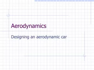
Advanced CFD Analysis of Aerodynamics Using CFX. Jorge Carregal Ferreira Achim Holzwarth, Florian Menter. Outline. CFX: Advanced CFD software The company The products Turbulence Modells in CFX Near wall treatment in CFX Examples: Duct with adverse pressure gradient Airfoils

E N D
Advanced CFD Analysis ofAerodynamics Using CFX Jorge Carregal Ferreira Achim Holzwarth, Florian Menter
Outline • CFX: Advanced CFD software • The company • The products • Turbulence Modells in CFX • Near wall treatment in CFX • Examples: • Duct with adverse pressure gradient • Airfoils • Heat transfer
Engineering Software Computational Fluid DynamiX Plant Simulation Software CFX: Member of AEA Technology
CFX: Global Position • CFD (Computational Fluid Dynamics) group of AEA Technology • Largest European CFD company • 210 employees • 8 main offices • Strong industrial presence • Growth rate approx. 25% per year • More than 1500 installed licenses
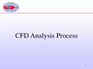
CFD-Analysis • Generate geometry: fluid domain • Generate mesh: discrete representation of fluid domain • Solve Navier-Stokes Equiations • Analyse Results • Coupling: Optimisation, fluid-structure coupling, accoustic analysis, design improvements
HEX TET WEDGE PYRAMID Leading Technology in CFX-5 • Easy to use • Pre-Processor CFX-Build based on MSC.Patran: • Unstructured hybrid grids • Coupled algebraic multigrid-solver (AMG): Accurate, robust and fast • Solution time scales linear with grid size • Excellent parallel performance • Grid adaptation • UNIX, NT, Linux
Leading Technology in CFX-5 • Laminar and turbulent flows. • Stationary and transient solutions. • Large variaty of turbulence models. • Transport equations for additional scalars. • Multi-component and multi-phase fluids. • Coupling with solid heat conduction. • Solution depended mesh adaptation. • Linear scaling of solver with grid size. • Scalable parallel performance.
Preprocessing with CFX-Build • Geometry modeller based • On MSC.Patran • Native CAD interfaces: • Pro/Engineer, CATIA, • Unigraphics, IDEAS, etc.
Turbulence Models in CFX-5 • Release of the latest turbulence models • k- Model Variants • k- Model and BSL Model (Wilcox, Menter) • SST Model (Menter, Blending between k- and k-) • Reynolds Stress Models • Extended near-wall treatments • Scalable wall functions for k- • Automatic near-wall treatment for k- and SST • LES model (Smagorinski) • Documented validation cases on these models are available • Future: Improved LES and transition modelling
Problems of Standard k- Model • Two Problems: • Missing transport effects. • Too large length scales. • Result: • Reduced or omitted separation. • Very often: Too optimistic machine performance.
Standard k- Model (Wilcox) • Advantages: • Lower length scales near wall. • Robust sublayer formulation (low-Re). • Problem: • Free stream sensitivity. • Has not replaced k- models.
k- Model Free Stream Problem Change of w in freestream Eddy viscosity profile Velocity profile
Optimal Two Equation Model • Combination of k-w and k-e model: • k-w model near the surface • k-e model for free shear flows (e equation is transformed to w) • Blending is performed automatically based on solution and distance from the surface. • This model is called “Baseline Model – BSL” • Combined with “Shear-Stress-Transport” limiter offers optimal boundary layer simulation capabilities. • BSL+Limiter gives SST model.
k-e model SST model Diffuser Flow, 1 Experiment Gersten et al.
Wall Boundary Treatment Standard wall function boundary conditions are the single most limiting factor in industrial CFD computations regarding accuracy! “y+ has to be between 25 and 500” type statements are problematic! • Boundary layer resolution requirements have to be satisfied. • Log. Profile assumptions have to be satisfied. • To satisfy both at the same time is the challenge.
Outer region Log. region Sub-layer Scaling of Variables near Wall
Flat Plate: Velocity Profile Intersection Finer Grids Standard Wall Function New Wall Function
Flate Plate: Wall Friction Finer Grids Finer Grids Standard Wall Function New Wall Function
Low-Re k- Model • Viscous sublayer resolution. • Simple formulation. • Numerically robust. • Grid resolution near wall y+<1-2. • Improved adverse pressure gradient behaviour. • Non-trivial boundary conditions. • Free stream dependency problem. • Blending possible.
. q=const . q=0 H Outlet D d Inlet axis 40 x H H Pipe Expansion with Heat Transfer Structured Grid (150.000 nodes) Reynolds Number ReD= 23210 Fully Developed Turbulent Flow at Inlet Experiments by Baughn et al. (1984)
Pipe Expansion with Heat Transfer k- Model, Standard Wall Functions
Pipe Expansion with Heat Transfer SST Model, Low-Re Wall Treatment
Pipe Expansion with Heat Transfer SST Model, Automatic Wall Treatment
Summary • CFX: Advanced CFD software • Fast and robust solver technology • Powerful Pre- and Postprocessing tools • Leading Turbulence Modells • Robust near wall treatment Allows for • Accurate solutions • Reliable Predictions