Download
1 / 95
1.2k likes | 1.75k Views
Fundamental Reference Systems. Dr. Brian Luzum Dr. George Kaplan Mr. John Bangert U.S. Naval Observatory. Outline. Reference Systems and Reference Frames Earth Orientation Parameters Time Software. Introduction to Reference Systems and Reference Frames. z. What is a Reference System?.

E N D
Fundamental Reference Systems Dr. Brian Luzum Dr. George Kaplan Mr. John Bangert U.S. Naval Observatory
Outline • Reference Systems and Reference Frames • Earth Orientation Parameters • Time • Software
z What is a Reference System? z y • A 4-D coordinate system • 3 spatial coordinates, 1 time coordinate • A mathematical abstraction that allows us to combine, compare, or otherwise relate positional measurements taken at different times and/or from different places • Defined by specification of • Origin of coordinates • Direction of axes • Standardized algorithms (software) that allow raw measurements to be transformed into the system • Some reference systems are defined by their relationship to others x z z z y x x
Primary Reference Systems Two primary reference systems are of interest: • Barycentric Celestial Reference System (BCRS) Also referred to as the International Celestial Reference System (ICRS) = The system of star catalog data replacing the “J2000.0 system” or the “FK5 system” • International Terrestrial Reference System (ITRS) = The world geodetic system = WGS-84 = GPS = Earth-Centered-Earth-Fixed (ECEF)
Today’s Problem: BCRS ITRS Celestial coordinates expressed in BCRS (ICRS) At any given time, what is the relationship? Terrestrial coordinates expressed in ITRS (ECEF)
How to transform vectors between the BCRS (ICRS) and the ITRS (ECEF) Vectors are sets of 4 numbers (3 spatial coordinates and 1 time coordinate) representing location (or its time derivatives) or direction (or its time derivatives) There are some intermediate reference systems that are often used as waypoints: BCRS GCRS CIRS TIRS ITRS Rephrased, Today’s Problem is . . . For Later! relativistic rotations transformation (a function of EOPs)
Real-World Applications • Looking up: In what direction is a ground-based sensor pointed? • Looking down: What spot on Earth will be “seen” by a space-based sensor? • Navigation: What is the position, velocity, acceleration, and/or rotation of a vehicle in inertial space? With respect to the ground?
A Few Ideas About the Primary Reference Systems • The orientation of the coordinate axes must be specified, in practice, by the position vectors of real objects “control points” or “anchors” • The ensemble of these defining objects, and their coordinates, are referred to as a “reference frame” The objects themselves are provided by nature; their assigned coordinates define the directions of the coordinate axes
Reference Frame Control Points Celestial Terrestrial Survey Markers Radio Galaxies Instrument Sites Stars
The Terrestrial Reference System • ITRS specifications: • Origin at geocenter (center of mass of Earth + oceans + atmosphere) • Relativistic “local Earth frame” with unit of time given by TCG second and unit of length given by SI meter • Direction of axes • Initially given by BIH system orientation at 1984.0 • Axes rotate with the crust — time evolution of orientation will create no residual global rotation with respect to the crust • Realizations — reference frames: • ITRFyyyy: 3-dimensional site coordinates and velocities (yyyy indicates year of solution; e.g., ITRF2005 or ITRF2008) • Site selection criteria: 3 years’ observations available, on rigid plates away from crustal deformations, velocities known to better than 3 mm/year
The Celestial Reference System • BCRS (ICRS) specifications: • Origin at solar system barycenter • Relativistic metric tensor specified in IAU resolution B1.3 of 2000 • Defining objects are unresolved, stationary, and stable extragalactic radio sources • Direction of axes • Fixed in space — do not rotate with respect to defining objects • “As near as possible” to system defined by the Earth mean equator and equinox of J2000.0 (i.e., ICRS “J2000.0 system”) • Independent of time and specific realizations (if the objects that define their direction eventually change) • Realizations two reference frames: • ICRF2: Catalog of 3414 extragalactic radio sources (295 defining sources) • HCRF: Catalog of ~100,000 stars from the Hipparcos catalog (85% of entire catalog; astrometrically well-behaved stars)
Densification of Reference Frames Addition of new control points, with coordinates consistent with those of defining points • Allows for higher spatial density • Allows for more even coverage of the Earth or celestial sphere • On the celestial sphere, allows for reference frame to be represented at wavelengths other than radio (=5 cm) or optical (=0.5 m) For example, IR, mm, or UV Continued…
Densification of Reference Frames (cont.) • On the Earth, any civilian GPS receiver effectively densifies the ITRF at 10-meter-level accuracy (a few meters or better for DGPS) • Celestial extensions of the ICRF and HCRF: • VLBA Calibrator Survey (VCS6) • Tycho-2 Catalog • UCAC2 (to V=16) and UCAC3 (UCAC4 in process) • USNO B1.0 • 2MASS (IR) • Solar system ephemerides (e.g., JPL DE405) aligned to ICRF Accuracy of representation varies considerably — Let the buyer beware!
Complications in Establishing Reference Frames • Problem is over-determined: only need two objects to define orientation of axes • Therefore, if N objects in a catalog, there are ~N2/2 independent reference frame definitions — which will not, in general, be consistent due to errors in coordinate values • Not too bad a problem as long as errors are random • If errors are a function of position, the reference frame is warped (systematic distortions) • Also problematic if errors are a function of other characteristics: • For stars, brightness or color • For Earth stations, type of instrument / technique
(2.37, +26.1) (–1.21, +22.8) (0.89, +18.4) (1.32, +5.9) (3.10, +1.7) (–2.05, –1.7) (1.52, –3.4)
(2.37, +26.1) (–1.21, +22.8) (0.89, +18.4) (3.10, +1.7) (–2.05, –1.7) (1.52, –3.4)
Using a warped reference frame — errors in coordinates a function of position
Using a warped reference frame — errors in coordinates a function of position Each measured position of the target is slightly wrong, because the star positions on which it is based are slightly wrong
What our tracking measurements actually mean Observed trajectory
What our tracking measurements seem to mean Observed trajectory
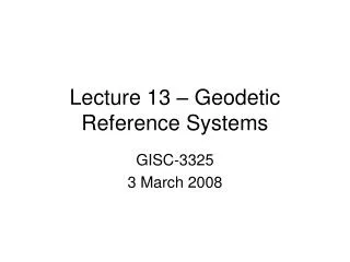
Why Star Positions, and the Reference Frames They Define, Degrade with Time 1950 1976 1990 Measured Path 2005 Actual Path
Even Many of the ICRF Radio Sources Seem to Move From USNO Radio Reference Frame Image Database (RRFID), A. Fey et al.
A Similar Problem with Terrestrial Frames — Stations Do Move
BCRS GCRS CIRS TIRS ITRS Finally: The Barycentric to Geocentric Transformation relativistic rotations transformation (a function of EOPs) How do we go from the Barycentric Celestial Reference System (BCRS) to the Geocentric Celestial Reference System (GCRS)? Note: GCRS = Earth-Centered Inertial (ECI) That is, how do we transform star coordinates from the solar system barycentric system of the star catalogs to the geocentric system in which we actually observe the stars on a given date?
BCRS and GCRS GCRS solar system barycenter BCRS
BCRS to GCRS Transformation • Positions in star catalogs represent where the stars would be seen from an idealized barycentric system at a certain epoch. To get observed geocentric coordinates of stars for a given date and time, they need to be adjusted for: • Orbital motion, if part of a binary or multiple system • Proper motion (3-D space velocity) • Parallax • Gravitational light deflection • Aberration of light • There are comparable adjustments for planetary or spacecraft ephemerides expressed in the BCRS Relativistic terms in the aberration formula effectively implement the BCRS to GCRS transformation
Why All This is Important • Any list of real objects and their coordinates defines a reference frame • It can be good, bad, or something in between • It may not be consistent with the ICRF or HCRF (for celestial coordinates) or the latest ITRF (for terrestrial coordinates) • If it is based on old data, its accuracy has probably degraded significantly • It is a bad idea to keep using some list of coordinates handed down from generation to generation • The FK5 is obsolete! • Please consult USNO!
Earth Orientation Parameters (EOP): Definitions and theiruse in transformations
Definition of Earth Orientation Parameters • Earth orientation parameters (EOPs) describe the direction of axes fixed to the Earth in space • used to transform between ground based coordinates (terrestrial reference frame) and “inertial” coordinates (celestial reference frame) • 5 EOPs • 2 polar motion (PM-x and PM-y) • 1 Earth rotation angle (UT1-UTC) • 2 celestial pole ( and or X and Y)
Three Aspects of Earth Rotation 1 1 Path of rotation axis in space (wrt GCRS) precession / nutation 2 Path of rotation axis across Earth’s crust (wrt ITRS) polar motion • Rotation angle UT1 All are functions of time 3
Two schemes for transforming between the ITRS and GCRS Polar Motion Frame Bias “OLD”: Nutation Sidereal Time Precession “NEW”: Precession + Nutation + Frame Bias Polar Motion Earth Rotation
Two schemes for transforming between the ITRS and GCRS Polar Motion Frame Bias “OLD”: Nutation Sidereal Time Precession “NEW”: Precession + Nutation + Frame Bias Polar Motion Earth Rotation
Polar Motion • Left-handed coordinate system • 2 dominant motions • Chandler wobble (430 d) • Annual wobble (365 d) • Other smaller amplitude stochastic motions • Causes of polar motion • Oceans (pressure>current) • Atmosphere (press.>wind) • Hydrology?
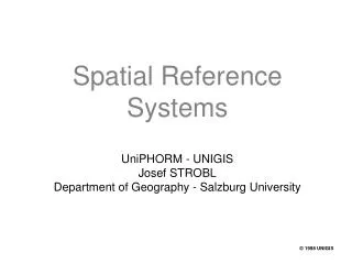
Spectrum POLAR MOTION Prograde Annual Wobble Power NUTATION ChandlerWobble Prograde Semi-annual Wobble Precession Nutations Free Core Nutation Atmospheric Tides -2 -1 1 2 0 Frequency in the Terrestrial Reference Frame (cycles per day) -1 0 1 2 3 Frequency in the Celestial Reference Frame (cycles per day)
Two schemes for transforming between the ITRS and GCRS Polar Motion Frame Bias “OLD”: Nutation Sidereal Time Precession “NEW”: Precession + Nutation + Frame Bias Polar Motion Earth Rotation
UT1-UTC • Dominant motions • Trend • Decadal • Annual/semiannual • Tidal • Other smaller amplitude motions • Causes of UT1-UTC • Tidal deceleration • Internal changes in inertia tensor • Atmosphere (winds) • Solid Earth tides
UT1-UTC Spectrum annual quasi-biennial oscillation atmospheric modes southern oscillation solid Earth and ocean tides semi -annual 40-50 -day oscillations Power monthly fortnightly decade fluctuations (from core?) atmospheric tides 0.1 year-1 0.2 year-1 1 year-1 0.1 month-1 Frequency
Leap Seconds • Leap seconds are a conventional attempt to align Earth rotation time (angle) with clock time (UTC) • |UT1-UTC| < 0.9 s • Leap seconds occur at end of June or December but the time between leap seconds is unpredictable • Expected to occur with increasing frequency • Problematic for operational systems • International Telecommunications Union (ITU) is considering a redefinition of UTC to eliminate leap seconds • UT1 and UTC would diverge
No impact if system doesn’t assume that UT1≈UTC, and makes no assumption regarding size of UT1-UTC Impact if system assumes that UT1≈UTC, or assumes a limit on the size of UT1-UTC Potential Impact of Leap Second Elimination
Suggestions Regarding Leap Second If you are using UT1≈UTC, need to determine impact of changing to input UT1-UTC into operational procedures If you assume numerical restrictions on UT1-UTC, need to determine impact on eliminating restrictions Any significant problem with operational procedures should be reported to USNO
Two schemes for transforming between the ITRS and GCRS Polar Motion Frame Bias “OLD”: Nutation Sidereal Time Precession “NEW”: Precession + Nutation + Frame Bias Polar Motion Earth Rotation
Precession and Nutation Precession / nutation: The changing direction of the Earth’s axis in space (now specifically with respect to the GCRS) due to torques exerted by the Moon, Sun, and planets • Precession: the long-term, smooth, secular motion 23.5° circle around the ecliptic pole in 25,800 years • Nutation: the smaller, short-term periodic motions Largest component: 18x12 arcsecond ellipse traced out in 18.6 years (Diagram from G. Beutler)
Celestial Pole • Dominant motions at frequencies • 18.6-year • Semiannual • Fortnightly • Causes of precession-nutation are gravitational pull of celestial bodies on the equatorial bulge of Earth • Very well determined • Small component not caused by gravity
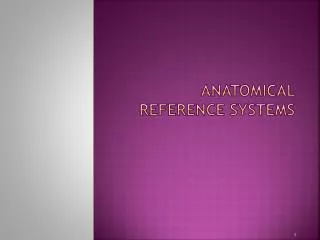
Celestial Pole Models • Since direction of celestial pole in space is affected mainly by gravitational attraction of Sun, Moon, and planets, it is very predictable • Current models IAU 2000 nutation and IAU 2006 precession • Residuals between models and observations (d and d or dX and dY) due to • Free Core Nutation (FCN) • Other variable amplitude terms (e.g. annual) • Errors in models • Estimated error in models ~0.5 mas
Precession / Nutation ObservationsLatest Results — wrt P03 / IAU2000A Model errors ~0.5 mas (Figure from Capitaine et al. 2008)
Celestial Pole Models • Older models IAU 1980 nutation and IAU 1976 precession • Residuals between models and observations (d and d) predominantly due to • Errors in models • Estimated error in models ~10 mas • Error is systematic, not random
Precession / Nutation ObservationsLate 90s Results — wrt Lieske / Wahr Model errors ~10 mas (Figure from Ma et al. 1998)
Basics • Concepts • Frequency • Repeatable phenomenon • Length of the time unit • Epoch • Naming convention • Sources of Time • Astronomy • Based on Earth’s rotation • Atomic Clocks • Based on frequency of an atomic transition