Download
1 / 62
620 likes | 739 Views
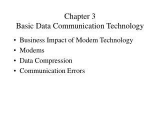
IT2101 : Communication Technology. 5.Transmission/ Network Media Program: BSCS I (January Semester – 2014) Lecturer: Rebecca Asiimwe Email: rasiimwe@technology.ucu.ac.ug. Network Media.

E N D
IT2101: Communication Technology 5.Transmission/ Network Media Program: BSCS I (January Semester – 2014)Lecturer: Rebecca Asiimwe Email: rasiimwe@technology.ucu.ac.ug
Network Media Network media is the actualpath over which an electronic signal travels as it moves from one component to another or one device to another.
Transmission Media • Numerous transmission media types are used for Data Communication • Generally categorized as: • Guided • Unguided (Wireless)
The Basics of Transmission The Transmitter generates and encodes data as energy which is transmitted through a medium. Transmitted energy is carried through some medium The medium can be copper, glass, air, etc
At the destination the energy is decoded back into data that can be used by the destination device. Energy can be electrical, light, radio etc. Note: Each form of energy has differentproperties and requirements for transmission.
Fundamental Limits of Transmission Media i) All channels allow only a limited set of frequencies to be passed. This limit is called bandwidth of that channel. • Bandwidth:Is the data transfer rate - the amount of data that can be carried from one point to another in a given time period (usually a second). • I.e., How much data is allowed to move through a medium usually per second.
Fundamental Limits of Transmission Media ii) All channels are subject to background noise (noise is unwanted electrical or electromagnetic energy that degrades the quality of signals and the data received).
Fundamental Limits of Transmission Media • NB:Sources of noise include: a) crosstalk: A signal on one line is picked up by adjacent lines as a small noise signal – For crosstalk, both cables / wires have the same strength.
b) Near-End Crosstalk • Caused when a strongtransmitter output signalinterferes with a much weaker incoming receiver signal. A strong wire Vs a weak energy wire, so the weak /lower strength cable is affected.
c)Impulse noise Caused by externalactivity or equipment which generates electricalimpulses. Can be caused by voltage spikes in equipment, lightening flashes, during thunderstorms and a wide variety of other phenomenon
Thermal noise (whitenoise): Caused by the thermal agitation of electrons associated with each atom in the device or transmission line material. Eg, electrical (“UMEME wire”) running parallel but near with the telephone wire. So, the thermal signals from the electrical wire might disorganize the telephone wire.
Additional Limitations of Transmission Media iii) SignalAttenuation: Is the phenomenon where the Amplitude/ strengthof a signal decreases as it propagates along a transmission line. -Attenuation is a function of distance and frequency of signal -Repeaters are used to increase the power of the signal at appropriate intervals.
Media Types Two categories a) Guided media b) Unguided • Guided Transmission Media uses a "cabling" system that guides the data signals along a specificpath. The data signals are bound by the "cabling" system. • Also known as Bound
Media Types • Guided Transmission Media include: • Fiber optics • Twisted pair cables • Coaxial cables
1) Twisted-Pair Cable • Twisted-paircable: Two of wires form a circuit that can transmit data. Cables are twisted to provide protection against crosstalk. • When two wires in an electrical circuit are placed close together, the magnetic fields are the exact opposite of each other. • The two magnetic fields cancel each other out. They also cancel out any outside magnetic fields. Twisting the wires can enhance this cancellationeffect.
Twisted pair cable • Can be a) Unshielded Twisted Pair (UTP) b) Shielded Twisted Pair (STP)
a) UTP UTP cable is a medium that is composed of pairs of wires. Used in a variety of networks. Each of the eight individual copper wires in UTP cable is covered by an insulating material.
UTP Cont’d UTP cable relies solely on the cancellation effect produced by the twisted wire pairs to limit signal degradation caused by electromagnetic interference (EMI) and radio frequency interference (RFI).
b) Shielded Twisted-Pair (STP) Combines the techniques of shielding, cancellation, and wire twisting. Each pair of wires is wrapped in a metallic foil. The four pairs of wires then are wrapped in an overall metallic braid or foil. Has a cancellation effect and a shield to prevent it from attacks like EMI.
STP UTP
Merits of the twisted pair technology • It is rather cost effective in comparison to other technologies like the fiber optic. • It is extremely easy to terminate. • Its thin and flexible and can be strung around walls • More lines can be run through the same connection ducts
Demerits of the twisted pair technology • It is prone to external interference. • They require many repeaters for relatively long distances which makes it expensive. • NB: The twisted pair technology uses A Registered Jack (RJ 45) in connections. • THE RJ-45 connector
2) Coaxial Cable Consists of a hollow outer cylindrical conductor that surrounds a single inner wire made of two conducting elements. One of these elements, located in the center of the cable, is a copperconductor. NB: e.g. those used on TV sets
3) Fiber-Optic Cable Uses glass (or plastic) threads (fibers) to transmit data. A fiber optic cable consists of a bundle of glassthreads, each of which is capable of transmitting messages as lightwaves
Parts of fiber optics • Core- Thin glass center of the fiber where the light travels • Cladding- Outer optical material surrounding the core that reflects the light back into the core • Buffer coating- Plastic coating that protects the fiber from damage and moisture
How fiber optics operate The light in a fiber-optic cable travels through the core (hallway) by constantly bouncing from the cladding (mirror-lined walls), a principle called total internal reflection. Because the cladding does not absorb any light from the core, the light wave can travel great distances.
Transmission is through electroluminescence (an optical phenomenon and electrical phenomenon in which a material emits light in response to the passage). • The emitted light is incoherent with a relatively wide spectral width of 30-60 nm. • Receivers- the main component of an optical receiver is a photo-detector that converts light into electric-signal through the photoelectric effect .
Transmitter-the most commonly-used optical transmittersare semiconductor devices such as light-emitting diodes (LEDs) and laser diodes.
Two types of fiber-optic cables a) Single-mode Allows only one mode of light to propagate through the fiber. Capable of higher bandwidth, and it is often used as a backbone - (10kms).
Multimode Multimode fiber cable allows multiple modes of light to propagate through the fiber. It uses light-emitting diodes (LEDs) as a light-generating device (2km)
Advantages • Fibers do not leak light and are quite difficult to tap (Secure). • Handles much higher bandwidth than copper wires. • The loss of signal in optical fiber is less than in copper wire. Repeaters are needed at 30 km Vs 5 for copper. • Not affected by electromagnetic interference. Unlike electrical signals in copper wires, light signals from one fiber do not interfere with those of other fibers in the same cable.
Disadvantages They are quite difficult to install Its an expensive technology - expensive to install. Very delicate / fragile.
b) Unguided Media-Wireless Communication Unguided Transmission Media refers to data signals that flow through the air. They are not guided or bound to a channel to follow. Unguided media provide a means for transmitting electromagnetic waves but do not guide them; examples are propagation through air, vacuum and sea-water.
Wireless communication Is the transfer of information over a distance with the use of electromagnetic waves. Electromagnetic waves are formed when an electric field couples with a magnetic field.
Example of unguided media • Radio wave transmission • Micro wave transmission • Light wave transmission
1. Radio transmission • The magnetic and electric fields of an electromagnetic wave are perpendicular to each other and to the direction of the wave • There are 3 types of RF (Radio Frequency) Propagation: • Ground Wave, • Ionospheric and • Line of Sight (LOS) Propagation.
Characteristics of radio transmission • Easily generated • Omni-directionally travel a long distance • Can penetrate building • Frequency dependant • Relatively low bandwidth for data communication • Tightly licensed by governments
i) Ground Wave Propagation Follows the curvature of the Earth. Ground Waves have carrier frequencies up to 2 MHz. AM radio is an example of Ground Wave Propagation. Radio, television and micro-waves are types of electromagnetic waves. They differ from each other in wavelength.
ii) Ionospheric Propagation Bounces off of the Earths Ionospheric Layer in the upper atmosphere. It is sometimes called Double Hop Propagation. It operates in the frequency range of 30 - 85 MHz
iii) Line of Sight Propagation • Line of Sight Propagation transmits exactly in the line of sight. The receive station must be in the view of the transmit station. It is sometimes called Space Waves or Tropospheric Propagation. • Examples of Line of Sight Propagation are: FM Radio, Microwave and Satellite.