Download
1 / 13
130 likes | 254 Views
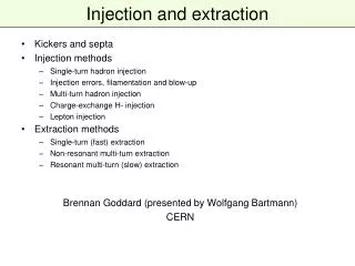
Injection and Extraction into/out of EMMA. Neil Marks, ASTeC, CCLRC Daresbury Laboratory, Warrington WA4 4AD, U.K. Tel: (44) (0)1925 603191 Fax: (44) (0)1925 603192 n.marks@dl.ac.uk. Electrical Engineering considerations. From Takei Yokoi’s presentation of 18/10/06 :

E N D
Injection and Extractioninto/out of EMMA Neil Marks, ASTeC, CCLRC Daresbury Laboratory, Warrington WA4 4AD, U.K. Tel: (44) (0)1925 603191 Fax: (44) (0)1925 603192 n.marks@dl.ac.uk
Electrical Engineering considerations • From Takei Yokoi’s presentation of 18/10/06 : • kicker aperture: 45 mm x 45 mm; • kicker length: 0.1 m; • kicker inductance: 130 nH. • For a kick of 0.1 radian, single turn magnet: • field in magnet: 0.035 T; • current at 10.5 MeV: 1.25 kA; • current at 20.5 MeV: 2.44 kA; • For turn-off/on in 20 ns: • voltage across magnet at 10.5 MeV: 7.9 kV; • voltage across magnet at 20.5 MeV: 15.4 kV
power supply magnet power supply magnet Magnet/Power Supply interface. • For kicker magnets, the power supply and magnet must be regarded as an indivisible system. • Two standard systems are used in accelerators: • The ‘matched delay line’: • The ‘close coupled’ system:
Problems with both circuits! • Matched delay-line problems: • the voltage wave propagating into the magnet is half the voltage of the power supply; • – so the power supply voltage is twice the magnet volts; • distributed capacitance must be added to the magnet • - the mechanical arrangements become complex; • consequently only used for large installations (CERN). • Close coupled system problems: • the inductance of the inter-connecting cables appears in series with that of the magnet; • so, power supply must be very close to the magnet.
2 b 2 a Interconnection Inductance. Inductance per unit length of two parallel conducting plates: Low frequency: • L= (m0/p){ (a/b) arctan (b/a) + loge [(b2 + a2)/b2]1/2 } H/m; • High frequency approximation: • L= m0 a /2b (pessimistic approximation) • eg at low frequency: for b = a: L = 300 nH/m; • for b = 2a: L = 266 nH/m; • at high frequency: for b = a: L = 630 nH/m; • for b = 2a: L = 315 nH/m; • for interconnection of 0.5m, this is ~ magnet inductance.
Power supply voltages • Conclusion for close coupled systems: • With best possible geometry: • L connections~ 3/4 L magnet • and: • V power supply ~ (1.75) V magnet • So, for kick of 0.1 radian power supply voltages will be: • injection: V power supply ~ 14 kV • extraction: V power supply ~ 27 kV • An increase in magnet inductance (ie length) would improve this!
Possible injection/extraction orbits • Using data from Scott Berg and Shinji Machida, rough approximate (thin lens) models of injection and extraction orbit geometries were assembled in EXCEL. • First task was to reproduce the undisturbed 10.5 MeV and 20.5 MeV orbits over two cells. • Because of thin lens approximation (probably), the exact parameters could not be replicated – small reductions in the quadrupole strengths gave close approximation to the original data. • The injection/extraction paths diagrams are proceeded by the undisturbed orbit models, used as a basis for the study.
D F D F Beam Undisturbed orbit at 10.5 MeV • Displacement (vertical axis) is relative to the 15.5 MeV reference orbit: Both axies are in mm; Positive displacement is radially outwards; Note that the orbit is traced backwards through the lattice. .
Single kick injection? Because of the position of the 10.5 MeV orbit, the injection from the inside of the ring, with a negative kick is more effective. In spite of a 0.15 radian kick, this does not look like a feasible solution.
+ ve kick - ve kick Two kick (adjacent long straights) injection. The addition of a positive kick in the long straight preceding the injection straight gives a feasible looking injection path. The beam would enter through the ‘window’ of the QF at x = 650 mm, with a magnetic shield. No septum is required. The 0.12 radian kicks require: I = 1.5 kA; V = 17 kV ( on the power supply).
Undisturbed orbit at 20.5 MeV Displacement (vertical axis) is relative to the 15.5 MeV orbit: Both axies are in mm; Positive displacement is radially outwards. Note that the orbit now is shown in the forward direction.
Septum magnet to be placed in this long straight. Extraction with a single kick and septum magnet. The kick of 0.12 radians at 20.5 MeV requires; I = 2.9 kA; V = 32.4 kV (on the power supply). This voltage is demanding but possible (?) The positioning of a septum magnet in the long straight after the extraction straight will need careful study.
Health Warning! • The orbit predications are made using simple, thin-lens algorithms and are intended to ‘point the way’ to satisfactory solutions with ‘achievable’ electrical engineering and not to give exact and accurate orbit positions; • they must be followed up by more accurate tracking studies with both the ideal orbit and the magnet field distributions predicted by Ben Shepherd; • the very short switching times represent a major problem and are outside the experience of any at DL (or RAL?); • the effect of stray capacitance has not been considered – it could result in very significant distortion to rise and fall times; • the injection and extractions systems represent major development exercises.