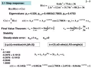
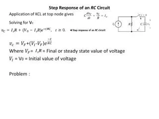
Download
1 / 23
230 likes | 303 Views
Step Response. Series RLC Network. Objective of Lecture. Derive the equations that relate the voltages across a resistor, an inductor, and a capacitor in series as: the unit step function associated with voltage or current source changes from 0 to 1 or

E N D
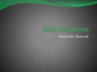
Step Response Series RLC Network
Objective of Lecture • Derive the equations that relate the voltages across a resistor, an inductor, and a capacitor in series as: • the unit step function associated with voltage or current source changes from 0 to 1 or • a switch connects a voltage or current source into the circuit. • Describe the solution to the 2nd order equations when the condition is: • Overdamped • Critically Damped • Underdamped
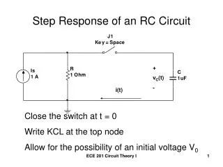
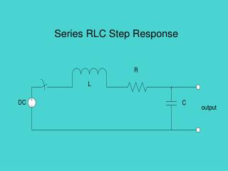
Series RLC Network • With a step function voltage source.
Boundary Conditions • You must determine the initial condition of the inductor and capacitor at t < to and then find the final conditions at t = ∞s. • Since the voltage source has a magnitude of 0V at t < to • i(to-) = iL(to-) = 0A and vC(to-) = 0V • vL(to-) = 0V and iC(to-) = 0A • Once the steady state is reached after the voltage source has a magnitude of Vs at t > to, replace the capacitor with an open circuit and the inductor with a short circuit. • i(∞s) = iL(∞s) = 0A and vC(∞s) = Vs • vL(∞s) = 0V and iC(∞s) = 0A
Selection of Parameter • Initial Conditions • i(to-) = iL(to-) = 0A and vC(to-) = 0V • vL(to-) = 0V and iC(to-) = 0A • Final Conditions • i(∞s) = iL(∞s) = 0A and vC(∞s) = Vs • vL(∞s) = 0V and iC(∞s) = 0A • Since the voltage across the capacitor is the only parameter that has a non-zero boundary condition, the first set of solutions will be for vC(t).
Set of Solutions when t > to • Similar to the solutions for the natural response, there are three different solutions. To determine which one to use, you need to calculate the natural angular frequency of the series RLC network and the term a.
Transient Solutions when t > to • Overdamped response (a > wo) where t-to = Dt • Critically damped response (a = wo) • Underdamped response (a < wo)
Steady State Solutions when t > to • The final condition of the voltages across the capacitor is the steady state solution. • vC(∞s) = Vs
Complete Solution when t > to • Overdamped response • Critically damped response • Underdamped response
Other Voltages and Currents • Once the voltage across the capacitor is known, the following equations for the case where t > to can be used to find:
Summary • The set of solutions when t > to for the voltage across the capacitor in a RLC network in series was obtained. • The final condition for the voltage across the capacitor is the steady state solution. • Selection of equations is determine by comparing the natural frequency woto a. • Coefficients are found by evaluating the equation and its first derivation at t = to- and t = ∞s. • The voltage across the capacitor is equal to the initial condition when t < to • Using the relationships between current and voltage, the current through the capacitor and the voltages and currents for the inductor and resistor can be calculated.
Step Response Parallel RLC Network
Objective of Lecture • Derive the equations that relate the voltages across a resistor, an inductor, and a capacitor in parallel as: • the unit step function associated with voltage or current source changes from 0 to 1 or • a switch connects a voltage or current source into the circuit. • Describe the solution to the 2nd order equations when the condition is: • Overdamped • Critically Damped • Underdamped
Parallel RLC Network • With a current source switched into the circuit at t= to.
Boundary Conditions • You must determine the initial condition of the inductor and capacitor at t < to and then find the final conditions at t = ∞s. • Since the voltage source has a magnitude of 0V at t < to • iL(to-) = 0A and v(to-) = vC(to-) = 0V • vL(to-) = 0V and iC(to-) = 0A • Once the steady state is reached after the voltage source has a magnitude of Vs at t > to, replace the capacitor with an open circuit and the inductor with a short circuit. • iL(∞s) = Is and v(∞s) = vC(∞s) = 0V • vL(∞s) = 0V and iC(∞s) = 0A
Selection of Parameter • Initial Conditions • iL(to-) = 0A and v(to-) = vC(to-) = 0V • vL(to-) = 0V and iC(to-) = 0A • Final Conditions • iL(∞s) = Is and v(∞s) = vC(∞s) = oV • vL(∞s) = 0V and iC(∞s) = 0A • Since the current through the inductor is the only parameter that has a non-zero boundary condition, the first set of solutions will be for iL(t).
Set of Solutions when t > to • Similar to the solutions for the natural response, there are three different solutions. To determine which one to use, you need to calculate the natural angular frequency of the parallel RLC network and the term a.
Transient Solutions when t > to • Overdamped response • Critically damped response • Underdamped response where
Other Voltages and Currents • Once the current through the inductor is known:
Complete Solution when t > to • Overdamped response • Critically damped response • Underdamped response
Summary • The set of solutions when t > to for the current through the inductor in a RLC network in parallel was obtained. • The final condition for the current through the inductor is the steady state solution. • Selection of equations is determine by comparing the natural frequency woto a. • Coefficients are found by evaluating the equation and its first derivation at t = to- and t = ∞s. • The current through the inductor is equal to the initial condition when t < to • Using the relationships between current and voltage, the voltage across the inductor and the voltages and currents for the capacitor and resistor can be calculated.