Download
1 / 27
440 likes | 1.28k Views
Chapter 2 Fundamentals of Rotor Aerodynamics SONG, Jianyu Outline 2.1 Introduction 2.2 Momentum Theory 2.3 Axial Climb and Descent 2.4 Momentum Analysis in Forward Flight 2.5 Chapter Review 2.6 Questions 2.1 Introduction Three functions of the rotor

E N D
Chapter 2 Fundamentals of Rotor Aerodynamics SONG, Jianyu
Outline 2.1 Introduction 2.2 Momentum Theory 2.3 Axial Climb and Descent 2.4 Momentum Analysis in Forward Flight 2.5 Chapter Review 2.6 Questions
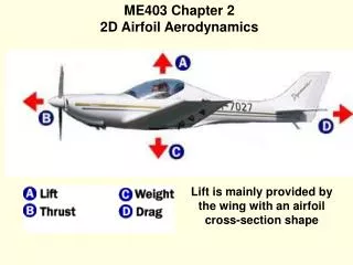
Three functions of the rotor • Vertical lifting force in opposition to the weight • Horizontal propulsive force for forward flight • Control the attitude and position of the helicopter • Fixed-wing vs. Helicopter • Separated vs. All three
Blade position: Azimuth angle In hovering flight In forward flight Free stream
Vortical Wake Fixed wing: uniform lift loading over the span Helicopter: high dynamic pressure at the blade tip =>strong vortices form And trial from each blade tip
Hover & Forward Hovering flight Forward flight • aircraft weight => Vertical lifting force • Aircraftweight & drag =>Tilting the plane of the rotor forward and increase the overall thrust • Asymetric velocity field => Cyclic pitch inputs
The overall aerodynamic complexity of forward flight Fixed-wing aircraft: Tip vortices trail downstream of the aircraft Forward flight helicopter: Blade tip vortices remain close to the rotor and to the following blades for several rotor revolutions =>a strongly three-dimensional induced velocity field =>fluctuating air loads on the blade =>affecting the rotor performance & source of vibration and noise
General • A variety of flight regimes: hover, climb, descent, forward flight • Hover and axial flight • The momentum theory approach allows one to derive a first-order prediction of the rotor thrust and power, and the principles also form a foundation for more elaborate treatments of the rotor aerodynamics problem.
2.2.1 Flow near a Hovering Rotor Hover: zero forward/vertical speed Rotor flow field is azimuthally axisymetric: There is a bake boundary or slipstream: a jump in pressure The contraction in the diameter: corresponding to an increase in the slipstream velocity
2.2.2 Conservation Laws of Fluid Mechanics Assume the flow through the rotor is: One dimensional Quasi-steady Incompressible Inviscid Conservation of fluid mass: Conservation of fluid momentum: Conservation of energy:
2.2.3 Application to a Hovering Rotor Different planes: By conservation of mass By Conservation of fluid momentum By Conservation of energy
Rotor Slipstream By conservation of mass The ratio of the cross-sectional area of the far wake to the area of the rotor disk By considering the radius The ratio 0.707 is called the “wake contraction ratio” Around 0.78 in experiment: a consequence of the viscosity of the fluid
Rotor Power By Conservation of fluid momentum T/A is known as the “disk loading” The power required to hover: This power is called “ideal power” One can alternatively write: Cube of the induced velocity: large rotor disk area and less velocity for the minimum induced power
Pressure Variation Since there is a pressure jump, Bernoulli’s equation can not apply across the disk. Between station 0 and 1 Between station 2 and ∞ Assume the jump is uniform. Pressure jump equals to disk loading We can further determine the pressure in terms of disk loading just above the disk just below the dick
2.2.4 Disk Loading and Power Loading Disk loading(DL):T/A Power loading(PL):T/P PL decreases quickly with increasing DL. Thus rotors with low DL will require a low power per unit thrust (high ideal PL) and will tend to be more efficien In reality, however, viscous losses should be considered Helicopter operate with low DL and is more efficient relative to other type of rotor aircrafts.
2.2.5 Induced Inflow Ratio • At the rotor disk, the induced velocity can be written as: • The nondimensional quantity is called the “induced inflow ratio in hover”. • For rotating-wing aircraft, it is the convention to nondimensionalize all velocities by the blade tip speed in hover.
2.2.6 Thrust and Power Coefficients • Thrust coefficient: • Relation of thrust coefficient and the and inflow ratio: • Power coefficient: • Relation with thrust coefficient: • Torque coefficient: • P=ΩQ. then it equals to Power coefficient • Other definition:
2.2.7 Nonideal Effects on Rotor Performance Simple modification of Eq 2.29 Κ: Induced power (correction) factor, and it is empirical coefficient. Profile power (include drag force) Assumed Cd is a constant Change to coefficient: NbcR/A is “rotor solidity”=the ratio of blade aero to rotor disk area The result of the modified theory
2.2.8 Figure of Merit Efficiency factor for helicopter: PL:T/P is a dimensional quantity Figure of merit as a nondimensional measurement is adopted It can also be written as: Measured figure of merit: Reason: higher profile drag coefficient and higher section of angle of attack Using modified theory:
2.2.10 Induced Tip Loss Tip loss phenomenon, especially at higher Tip loss factor B At higher effective DL: Empirical tip-loss factor base on blade geometry along:
2.2.11 Rotor Solidity and Blade Loading Coefficient • Higher values of FM are obtained with the lowest possible solidity at the same design CT • Empirical tip-loss factor base on blade geometry along: • Blade loading coefficient • Empirical tip-loss factor base on blade geometry along:
2.2.12 Power Loading Optimizing the rotor for maximum hovering efficiency can also have some trade-offs in terms of efficient high speed forward flight performance. Using modified momentum theory: We can also write: