Download
1 / 67
840 likes | 2.2k Views
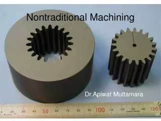
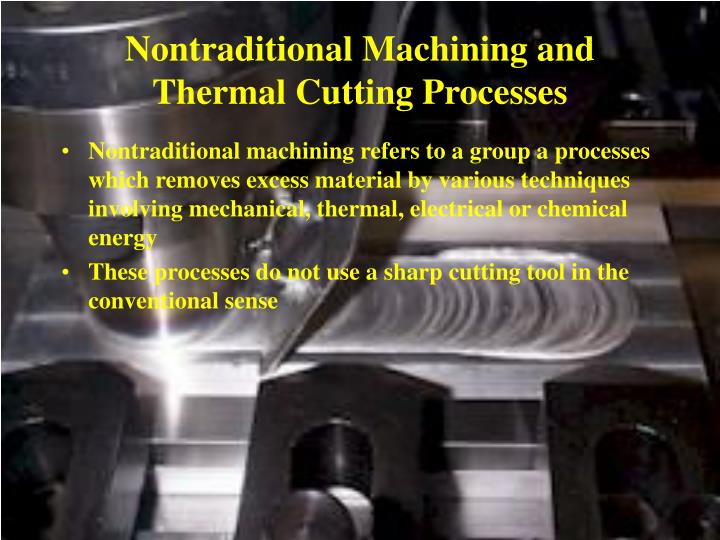
Nontraditional Machining and Thermal Cutting Processes. Nontraditional machining refers to a group a processes which removes excess material by various techniques involving mechanical, thermal, electrical or chemical energy

E N D
Nontraditional Machining and Thermal Cutting Processes • Nontraditional machining refers to a group a processes which removes excess material by various techniques involving mechanical, thermal, electrical or chemical energy • These processes do not use a sharp cutting tool in the conventional sense
Nontraditional processes have been developed in response to new and unusual machining requirements, including • The need to machine newly developed materials with special properties (high strength, high hardness, high toughness) • The need for unusual and/or complex geometries • The need to avoid surface damage
Classification of nontraditional manufacturing processes by principle form of energy • Mechanical - mechanical energy in some form different from the action of a conventional cutting tool; erosion of the workpiece material is typical • Electrical - electrochemical energy to remove material
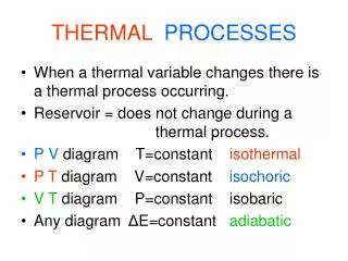
Thermal - thermal energy generally applied to a small portion of the work surface, causing removal by fusion and/or vaporization; thermal energy is generated by conversion of electrical energy • Chemical - most materials are susceptible to chemical attack by certain acids or other etchants; chemicals selectively remove material from portions of the workpiece, while other portions of the surface are protected
Available nontraditional material removal processes • Mechanical • AFM - abrasive flow machining • AJM - abrasive jet machining • HDM - hydrodynamic machining • LSG - low stress grinding • RUM - rotary ultrasonic machining • TAM - thermally assisted machining • TFM - total form machining • USM - ultrasonic machining • WJM - water jet machining
Electrical • ECD - electrochemical deburring • ECDG - electrochemical discharge grinding • ECG - electrochemical grinding • ECH - electrochemical honing • ECM - electrochemical machining • ECP - electrochemical polishing • ECS - electrochemical sharpening • ECT - electrochemical turning • ES - electro-stream • STEM - shaped tube electrolytic machining
Thermal • EBM - electron beam machining • EDG - electrical discharge grinding • EDM - electrical discharge machining • EDS - electrical discharge sawing • EDWC - electrical discharge wire cutting • LBM - laser beam machining • LBT - laser beam torch • PBM - plasma beam machining
Chemical • CHM - chemical machining • ELP - electropolish • PCM - photochemical machining • TCM - thermochemical machining • TEM - thermal energy machining • While many processes are available, only the most commercially important processes are discussed here
Mechanical Energy Processes • Ultrasonic machining (USM) • Abrasives contained in a slurry are driven at high velocity against the work by a tool vibrating at low amplitude (.003in) and high frequency (20-100khz) • The tool oscillates in a direction perpendicular to the workpiece surface and is fed slowly into the workpiece so that the shape of the tool is formed in the part
The action of the abrasives impinging against the work surface performs the cutting • Tool materials - soft steel, stainless steel • Abrasive materials - boron nitride, boron carbide, aluminum oxide, silicon carbide and diamond • The vibration amplitude should be set approximately equal to the grit size, and the gap size should be maintained at about two times the grit size
The ratio of work material to tool material removed during the cutting process ranges from ~100:1 for cutting glass down to ~1:1 for cutting tool steel • Workpiece materials: hard and brittle such as ceramics, glass and carbides; successfully used on certain metals such as stainless steel and titanium • Shapes obtained by USM include nonround holes, holes along a curved axis and coining operation, in which an image pattern on the tool is imparted to a flat work surface
Water jet cutting (WJC) • Nozzle diameter: 0.004-0.016 in • Pressure: up to 60,000psi • Jet velocity: up to 3000 ft.Sec • Nozzle made of sapphire, ruby or diamond • Cutting fluids: polymer solutions; preferred because of their tendency to produce a coherent stream
Important process parameters: standoff distance, nozzle operating diameter, water pressure and cutting feed rate • Typical feed rates: 12 in/min to well over 1200 in/min • The water jet cutting process is usually automated using CNC robots to manipulate the nozzle unit along the desired trajectory • Materials cut by water jet: plastic, textile, composites, tiles, carpet, leather and cardboard
Advantages: no crushing or burning of the work surface, minimum material loss because of the narrow cut slit, no environmental pollution, and easy automating the process • Limitation: not suitable to cut brittle material because of their tendency to crack during cutting
Abrasive water jet cutting (AWJC) • Introduction of abrasive particles into the stream adds to the number of parameters that must be controlled; among these are: abrasive type, grit size and flow rate • Type of abrasive materials: aluminum, oxide, silicon dioxide and garnet (a silicate mineral) • Grit size: ranges between 60 and 120 • Flow rate: approximately 0.5 lb/min • Nozzle orifice diameter: 0.010 - 0.025in; somewhat larger that in water jet cutting to permit higher flow rates and more energy to be contained in the stream prior to the infection of abrasives
Abrasive jet machining (AJM) • A high velocity stream of gas containing small abrasive particles • Pressure: 25 - 200 psi • Nozzle orifice diameter: 0.003 - 0.040 in • Velocities: 500 - 1000 ft/min • Gases: dry air, nitrogen, carbon dioxide and helium • The process is usually carried out manually by an operator • AJM is normally used as a finishing process • Applications: deburring, trimming and deflashing, cleaning and polishing • Applied on hard, brittle materials (glass, silicon, mica and ceramics) that are in the form of thin flat stock • Typical abrasives: aluminum oxide (for aluminum and brass), silicon carbide (for stainless steel and ceramics), and glass beads (for polishing)
Grit sizes are small, 15-40m in diameter and must be very uniform in size for a given application • No recycling of abrasives; abrasive grains are fractured, worn and contaminated
Electrochemical Machining Processes • Electrochemical machining (ECM) • It removes metal from an electrically conductive workpiece by anodic dissolution, in which the shape of the workpiece is obtained by a formed electrode tool in close proximity to, but separated from the work by a rapidly flowing electrolyte • Underlying principle: material is deplated from the anode and deposited onto the cathode in the presence of an electrolyte bath
The difference in ECM is that the electrolyte bath flows rapidly between the two poles to carry off the deplated material • The electrode tool, usually made of copper, brass or stainless steel, is designed to posses approximately the inverse of the desired final shape of the part • Gap distance: usually from 0.003 - 0.030 in • A water solution of sodium chloride is commonly used as the electrolyte
Electrolyte serves for: • Carrying off the material that has been removed from the workpiece • Removing hear and hydrogen bubbles created in the chemical reactions of the process • Removed material in the form of microscopic particles must be separated from the electrolyte through centrifuge, sedimentation or other means • Large amount of electrical power is required to perform ECM
Voltage is kept relatively low to minimize arcing across the gap • Use when: • The material is very hard or difficult to machine or • Where the workpiece geometry is difficult or impossible to accomplish by conventional machining methods • Typical ECM applications • Die sinking • Multiple hole drilling • Holes that are not round • Deburring
Advantages: • Little surface damage to the work part • No burrs as in conventional machining • Low tool wear • Relatively high metal removal rates for hard and difficult to machine metals • Disadvantages • Significant cost of electrical power to drive the operation • Problems of disposing of the electrolyte sludge
Electrochemical deburring (ECD) • An adaptation of ECM designed to remove burrs or round sharp corners • The same ECM principles of operation apply to ECD • Much less material is removed in ECD, thus cycle times are much shorter
Electrochemical grinding (ECG) • Special form of ECM • A rotating grinding wheel with a conductive bond material is used to augment the anodic dissolution of the metal workpart surface • Bond material: metallic (diamond abrasives) or resin bond impregnated with metal particles (aluminum oxide) • Most of the machining is accomplished by electrochemical action, therefore the grinding wheel lasts much longer
Applications: • Sharpening of cemented carbide tools • Grinding of surgical needles, other thin wall tubes and fragile parts
Thermal Energy Processes • Electric discharge machining (EDM) • One of the most widely used nontraditional processes • Shape of the finished work surface is produced by a formed electrode tool • EDM process must take place in the presence of a dielectric fluid
Discharge region heated to extremely high temperature so that a small portion of the work surface is melted and removed • Individual discharges occur hundreds or thousands of times per second to give a gradual erosion of the entire surface • Process variables: • Discharge current • Frequency of discharges
The high spark temperature causes the tool to melt, resulting in a small cavity opposite the cavity produced in the work • Wear ratio: • Work material removed/tool material removed • Ranges from 1.0 - 100 depending on the combination of work and electrode materials • Electrode materials: graphite, copper, brass, copper tungsten, silver tungsten, etc. • Metal removal rate: • MRR = KI/Tm1.23
Dielectric fluids used: hydrocarbon oils, kerosene and distilled or deionized water • Applications: • tool fabrication and parts production • delicate parts • hole drilling with hole axis at an acute angle to the surface • production machining of hard and exotic metals
Electric Discharge Wire Cutting (EDWC or wire EDM) • special form of EDM using a wire as the electrode • cutting action achieved by thermal energy from electric discharges between the electrode wire and the workpiece
Workpiece fed continuously and slowly past the wire to achieve cutting path • NC used to control workpart motions • Wire EDM must be carried out in the presence of a dielectric • Wire diameters: 0.003 - 0.012 in. • Wire materials: brass, copper, tungsten and molybdenum • Dielectric fluids: deionized water or oil
Overcut ranges from 0.0008 - 0.002in. And remains fairly constant and predictable once cutting conditions are established
Electron Beam Machining (EBM) • A high velocity stream of electrons is focused on the workpiece surface to remove material by melting and vaporization • Electron beam gun accelerates a stream of electrons to ~3/4 c and focused through an electromagnetic lens • Kinetic energy of beam converted to thermal energy of extremely high density, melting or vaporizing material in a very localized area • EBM must be carried out in a vacuum
Can be used on any known material • Applications: • drilling of extremely small diameter holes - down to 0.002 in • drilling holes with high depth/diameter ratios, greater than 100:1 • Limitations: • need of a vacuum • high energy required • expensive equipment
Laser Beam Machining (LBM) • Uses light energy from a laser to remove materials by vaporization and ablation • Types of lasers: • CO2 • solid-state • Energy is concentrated optically and in terms of time • Light beam pulsed so that the released energy results in an impulse against the work surface, producing evaporation and melting
Used for: • drilling - down to 0.001 in • slitting • slotting • scribing • marking • Not considered a mass production process; generally used on thin stock • Range of work materials virtually unlimited
Plasma Arc Cutting (PAC) • Plasma - a superheated, electrically ionized gas • PAC uses a plasma stream operating at temperatures in the range from 18,000o - 25,000o F to cut metal • The high-velocity plasma stream is directed at the workpiece, melting it and blowing the molten metal through the kerf
Plasma arc generated between an electrode inside the torch • Plasma flows through a water-cooled nozzle, which constricts and directs the stream • Hot enough to cut through metal 6 in thick • Gases used: • nitrogen, argon-hydrogen or a mixture (primary gases) • secondary gases or water directed to surround the plasma jet to confine the arc and clean the kerf
Most applications consist of cutting flat metal sheets and plates • Can be used to cut nearly any electrically conductive metal • Feed rates: • as high as 430 in/min for 1/4 in. aluminum • 200 in/min for 1/4 in. steel • 20 in/min for 4 in. aluminum
Advantage: high productivity • Disadvantages: rough cut surface, metallurgical damage
Air Carbon Arc Cutting • arc generated between a carbon electrode and the metallic work • High-velocity air jet used to blow away the melted portion of the metal • Used to form a kerf for severing the piece or to gouge a cavity in the pat • Used on a variety of metals, including cast iron, carbon steel, low alloy and stainless steels • Sputtering of molten metal is a hazard