Download
1 / 32
320 likes | 420 Views
Dr. Y.V. Bogdanova Recent researches. Contents: 1. Plasma composition in the cusp region observed by CIS onboard Cluster. 2. Plasma composition in the LLBL region observed by CIS onboard Cluster. 3. Oxygen beams in the cusp and polar cap regions.

E N D
Dr. Y.V. Bogdanova Recent researches Contents: 1. Plasma composition in the cusp region observed by CIS onboard Cluster. 2. Plasma composition in the LLBL region observed by CIS onboard Cluster. 3. Oxygen beams in the cusp and polar cap regions. 4. Present research: statistical estimation of the size of the source of the O+ upwelling ions in the cusp-cleft region. Study of ions energy step structures in the cusp region.
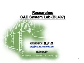
Cusp observation during commissioning phase ,October 01, 2000, S/C 3 and 4, Satellites orbit Cluster orbit, 01 October 2000, 12:20-12:50 UT, S/C velocity: 4,2-4,8 km/s, R=4,4-5,3 Re The CLUSTER Ion Spectrometry (CIS) instruments provide 3D ion distribution functions for the major ion species H+, He++, He+, and O+ in the energy range 5 eV to 40 keV . During commissioning phase there were a few mid-altitude cusp observations by CIS instrument onboard Cluster. Here is one example of such observation, made during October 01, 2000, 12:20-12:50 UT, during this event CIS data from S/C 3 and S/C 4 were available. Figure shows satellites orbit during this time: the S/C were crossing the northern cusp and moved from the dayside magnetosphere into the lobe. There was rather quite geomagnetic activity (Kp=2) and Bz-component of IMF measured with the Wind spacecraft during all day was around zero. EGS, 2001
Cusp observation during commissioning phase ,October 01, 2000, S/C 3 and 4, CIS spectrograms and 3D-moments for H+ • Left figure presents spectrograms from the CODIF instrument for different ions for S/C 3 and S/C 4. There is an energy-latitude dispersion, the energy of precipitating ions in the cusp region decreases with latitude. This effect is usually interpreted as a velocity filter effect connected with reconnection at the magnetopause. There are also small energy steps, which can be explained in the framework of impulsive reconnection model. • Right figure shows 3D-moments measured on S/C 3: number density, velocity, temperature and heating flux. The cusp is a clearly distinguished region, usually it’s characterized by sharp increases of plasma density, at the same time temperature and velocity are not very high. EGS, 2001
Cusp observation during commissioning phase, October 01, 2000, S/C 3 and 4, Proton fluxes as function of elevation angle • Thesefigures presents proton fluxes measured with CODIF experiment onboard S/C 3 and 4 versus elevation angle for different energy ranges. In the northern hemisphere CIS is observing an inflow of particles for <0 and an outflow of particles for >0. There is an almost isotropic distribution of protons (fluxes measured for >0 are equal fluxes for <0), however upward flowing low-energy protons are observed in the energy range 20-150 eV/e during all time cusp crossing. • The proton distributions measured by the two spacecraft have some differences. S/C 3 started to cross the equatorward edge of the cusp at 12:22 UT and we can see small-scale structures – three narrow beams protons populations during 12:22-12:25 UT. The duration of satellite crossing of these narrow regions is around 20 seconds and we can estimate the size of these regions as around 100 km for each region. At 12:26 UT a sharp increase of the proton fluxes is observed. The distance between S/C 3 and S/C 4 during this time was around 600 km, and S/C 4 crossed the equatorward edge of the cusp 3 minutes later, at 12:25 UT. We can observe in S/C 4 the following plasma structure – first a narrow plasma region almost without modification, and two regions with smoothing and increasing proton fluxes, and after that at 12:29 UT a sharp increase of flux. Note that all these plasma structures have isotropic proton distributions and sharp boundaries simultaneously at all energy ranges. Because of the similar structures seen by S/C 3 and S/C 4 the observations are compatible with small-scale filamentary plasma structures in the cusp region. EGS, 2001
LLBL observation by CIS Cluster,January 31, 2001, Cluster orbit Cluster orbit, January 31, 2001, 01:00-08:00 UT Observations of the ion composition in the low-latitude boundary layer (LLBL) obtained by the CIS experiment onboard Cluster during 31st of January 2001, 02:15-06:20 UT is presented. During this time S/C had a orbit: cusp, LLBL, magnetopause, magnetosheath ( see figure). CIS data shows that LLBL was beginning in the altitude around 10 Re. Data from ACE shows that during this time there were very quite interplanetary conditions, Bz-component of IMF was slightly positive and stable during 8 hours. AGU, spring 2001
LLBL observation by CIS Cluster,January 31, 2001, CIS data overview • The three figures present spectrograms for H+, O+, He++, and He+ from S/C 1, 3, and 4. Interesting for us period is 02:15-06:10 UT. During this time we see high-energy population of protons with energy around 1keV – this is plasma sheet population. We can see low-energy H+ population with energy around 50 eV, from ionosphere. Both plasma populations are isotropic. • In the O+ spectrograms we see low-energy oxygen with maximum energy around 200 eV, with two periods of intensive injection of particles, 02:45-03:45 UT, and 04:15-05:00 UT. From pitch-angle distribution (not shown here) we can see, that during these periods there were outflowing O+ beams. Also we see low-energetic He+, with isotropic distribution. AGU, spring 2001
LLBL observation by CIS Cluster,January 31, 2001, 3D-moments for H+ and O+ Above figurespresent 3D-moments for H+ and O+, respectively: density, velocity, temperature and heating flux. We see: o Density of proton plasma is around 0.2 cm-3, and increases up to 10 cm-3 (data from CIS-2) when S/C is going to the magnetosheath. o Density of oxygen is around 0.02 cm-3, and increases during outflowing beams up to 0.2 cm-3. o The velocity of protons is small and variable, without distinguishable direction. o The Vz-component of oxygen velocity is positive, indicating oxygen outflow from ionosphere. o LLBL region is stating with sharp increasing of temperature, up to 4000 eV for proton and 3000 eV for oxygen. Proton temperature has an anisotropy:parallel temperature is smaller than perpendicular. AGU, spring 2001
LLBL observation by CIS Cluster,January 31, 2001, Energy dependence of proton flux • Figurepresents the protons flux as function of energy for different regions: for the cusp (left top panel), for the magnetosheath (right top panel) and for the LLBL region (bottom panels). Data were averaged over 5 minutes. • We see: • 1. In the cusp region there are two energy peaks, one at 50 eV, and another one at 200 eV. • 2. In the magnetosheath in this case there is one energy peak, at 200 eV. 3. In the LLBL region there are two clear energy peaks, first at 50 eV, and second at 2000 eV. The first peak corresponds to plasma of ionospheric origin. The second peak corresponds to a plasma population from plasma sheet origin. We can see also small peak at 200 eV, which corresponds to plasma from magnetosheath origin. AGU, spring 2001
LLBL observation by CIS Cluster,January 31, 2001, Distribution function for protons The left figure is organized in the following way: top left panel – shows the distribution function in the cusp region, for total energy range, right bottom panel – in the magnetosheath region, for total energy range, another two panels – in the LLBL region, for the hot population of plasma, 1 keV – 32 keV. We see typical distribution functions for these regions. In the LLBL region there is some anisotropy, probably corresponding to the motion of trapped particles. The right figure shows distribution functions in the LLBL region for cold plasma population with energy range 23.7 eV-1keV. We see almost isotropic distribution for low-energy protons. AGU, spring 2001
LLBL observation by CIS Cluster,January 31, 2001, Summary Detailed data from the CIS experiment onboard Cluster II for one low-latitude boundary layer region (31st of January) crossing is presented. Our investigation shows the following features of LLBL: • LLBL was beginning at the altitude around 10 RE. · In this region we have seen high turbulent mixed plasma from three origins: ionosphere, plasma sheet, and magnetosheath. · This region contains rarefied plasma: density of protons is around 0.2 cm-2, and oxygen density is around 0.02 cm-2. · The temperature in this region is very high, up to 4000 eV, which corresponds to plasma sheet population. During the injection of ionospheric plasma temperature decreases. Proton temperature has anisotropy. · Protons in this region have three energy peaks. First at 50 eV, related to plasma outflow from the ionosphere; second at 200 eV, related to plasma of magnetosheath origin, and third with maximum flux at 2000 eV, this is typical value for plasma from plasma sheet. · The distribution function for protons shows a small anisotropy for the high-energy population, probably due to contribution from trapped particles. AGU, spring 2001
Oxygen beam observation in the cusp and polar cap regions, March 04 2001, CIS data overview One example of the oxygen beam in the high-altitude cusp and polar cap region, CODIF energy-time spectrograms for 04 March, 2001, 21:30-24:00 UT from S/C 1, 3, 4 for H+ and O+. Proton distribution is a typical for the cusp region and has energy-time dispersion with a few energy steps which usually are interpreted as a results of a new pulses of the reconnection in the magnetopause. The similar O+ beams were observed at three S/C with the following features: beam ions have a very narrow energy distribution, shows an energy dispersion from 1-2 keV in the cusp region to the 20-40 eV in the polar cap and O+ energy distribution tracks the upper limit of the H+ population in the energy-time spectrogram. AGU, fall 2001
Oxygen beam observation in the cusp and polar cap regions,March 04 2001, S/C orbit, AE-index, IMF condition Cluster orbit, March 04,2001, 21:45-23:45 UT • The S/C moved from dayside to the nightside in the X-direction over cusp and polar cap regions, and closer to the Earth in the Y- and Z-directions. The separation distance between S/C was around 750 km. In the X-direction the satellites moved in the following sequences: S/C 1 was first, S/C 4 – second, S/C 3 third. AE index indicates a high geomagnetic activity with a few subsequent big substorms. Solar wind and IMF condition measured on ACE show that during several hours there were stable conditions in the solar wind and the Bz-component of IMF was strong negative. Conclusion: an oxygen beam was observed during the time with high substorm activity and with good condition for reconnection in the dayside magnetopause. AGU, fall 2001
Oxygen beam observation in the cusp and polar cap regions,Statistics Oxygen beams were observed frequently during spring 2001. All beam observations were made during times with moderate and high geomagnetic activity: Kp=1-6. Comparison with IMF data from ACE shows that from 14 events: 9 events were observed during times with stable strong negative Bz-component of IMF (blue color in the table), 4 events – during times with very unstable conditions in the solar wind (magenta), and 1 event – during time with positive Bz-component and extremely high By-component. Conclusion: all beam observations were made during times with favourite conditions for dayside reconnection. AGU, fall 2001
Oxygen beam observation in the cusp and polar cap regions,March 04 2001, O+ 3D-moments • Oxygen spectrogram (a) from S/C 3 and oxygen density (b) and velocities (c, d) from S/C 1, 3, 4 (black, green, blue): • The beam is first observed at 21:45 UT in the cusp region with energy ~ 1keV with a gradual decrease of the energy with time to ~ 50 eV at 23:30 UT. In the cusp there are two O+ populations: low-energy O+ ions which are typical for the cusp and high-energy beam ions. • The O+ density slightly increases with time and varies from n~0.1-0.3 cm -3 . The densities on three S/C show very similar behavior. • The parallel to the magnetic field velocity (c) decreases with time and after 22:30 UT (in the polar cap) the velocities measured on three S/C have very similar behavior. In the cusp region velocity measured on S/C 1 is smaller that the velocities measured on S/C 3, 4. This could be due to temporal variations or differences in the source region of ions. • The perpendicular to the magnetic field O+ velocities (d) measured on three S/C are extremely similar. Vx was almost time negative, so it was tailward convection. AGU, fall 2001
Oxygen beam observation in the cusp and polar cap regions, March 04 2001, comparison with EDI data • The top figure shows the O+ in a distribution function representation. It again shows the narrow energy range of the beam and the energy decreases with time: Et3<Et2<Et1. • The bottom figure shows a spectrogram and the velocity components of the O+ beam measured on S/C 3. The vertical lines mark the times which have been used for the calculation of the distribution function. • The bottom panel presents a comparison of CIS data with Electron Drift Instrument (EDI) data. Vx of the oxygen velocity determined by CIS is in a good agreement with the plasma convection velocity measured directly by EDI. • We can conclude that the oxygen motion is a superposition of the outflow of accelerated ionospheric ions along magnetic fled lines with velocity VII and tailward plasma convection with velocity Vx. AGU, fall 2001
Oxygen beam observation in the cusp and polar cap regions,March 04 2001, Schematic illustration Upwelling O+ ions from the cleft region were observed first 15 years ago on DE 1 satellites ( Lockwood et al., 1985; Moore et al, 1986). The energy - time dispersion of the O+ beam can be interpreted by a similar mechanism. Accelerated O+ ions of ionospheric origin and from a spatially (in latitude) very localized source propagate outward parallel to the magnetic field. At the same time the field lines are convected tailward as expected for reconnection at the dayside magnetopause. The superposition of parallel flow and tailward convection leads to the apparent narrow distribution in energy and angle. Thus, the energy - time dispersion is a natural consequence of slower O+ ions arriving later at the point of observation. AGU, fall 2001
Oxygen beam observation in the cusp and polar cap regions,March 04, 2001 The left figure shows characteristic variations (sharp increases) of V, simultaneously on all S/C, indicating large scale variations of the convection pattern. These variations are related to large changes in the Bx-component of the magnetic field. The right figure present correlation of convection velocities directly measured by EDI with high time resolution (1s). A correlation shows that this similarity of V even holds for times of 1 s. AGU, fall 2001
Oxygen beam observation in the cusp and polar cap region,March 04 2001, Summary • During February-May 2001 O+ beams are frequently observed. • The main features of the event on March 04 are: 1. Narrow distribution in energy and angle. 2. Energy-time dispersion, with energy decreasing from ~ 1keV to 50 eV in the polar cap. 3. X-component of the perpendicular velocity of O+ indicates tailward convection. 4. Vx determined for O+ agrees well with Vx directly measured by EDI. 5. V as determined at different spacecraft are very similar, indicating similar plasma convection on the spatial scale of s/c separation (~750 km). • The O+ observations can be explained by a localized source of accelerated ionospheric ions with velocity V, determined by the superposition of outward particle motion VII with tailward convection V. • Comparison with IMF data shows that oxygen beams were detected during times with favourable conditions for magnetopause reconnection. • It is demonstrated that the O+ beams can be used as a valuable tool for the investigation of convection in the polar cap and tail-lobe region. AGU, fall 2001
Oxygen beam observation in the cusp and polar cap regions,May 18, 2001, CIS data overview • The figure shows energy-time spectrograms for H+ and O+ from the S/C 1, 3 and 4 for May 18, 2001, 02:00-04:00 UT. • The H+ population shows the typical cusp distribution with energy dispersion and several energy steps, at the end – magnetosheath particle distribution. The magnetopause crossing is marked by dashed blue lines. • In the oxygen spectrograms we can see a O+ beam with the following features: the oxygen beam population ‘tracks’ the upper edge of the H+ population in the energy flux spectrogram, has a very narrow energy range, and shows energy dispersion from 1-2 keV in the cusp region to 20-40 eV in the polar cap • The separation distances between S/C were rather high, 1-3 Re, and this gives us unique possibility to estimate the spatial size of the oxygen source in the cusp region and to study the spatial variations of the oxygen outflow. EGS, 2002
Oxygen beam observation in the cusp and polar cap regions,May 18, 2001, Solar wind and IMF conditions • Data from ACE: interplanetary magnetic filed, velocity and density of solar wind. The dashed line shows the beginning of the time period of interest for us, about 1 hour before the Cluster observations. During this time there were very unstable interplanetary conditions: the Bz-component of the IMF varies from negative to positive values five times. EGS, 2002
Oxygen beam observation in the cusp and polar cap regions,May 18, 2001, S/C orbit and AE index. • The left figure presents the satellite orbit during 18 May 02:00-04:00 UT. The S/C moved through the northern polar cap and cusp regions from the nightside to the dayside in the X-direction and away from the Earth in the Y- and Z-directions. • The right figure shows the AE-index for 18 May. During 02:00-04:00 UT there was high geomagnetic activity with a few subsequent substorms, the Kp-index was 3-. EGS, 2002
Oxygen beam observation in the cusp and polar cap regions,May 18, 2001, S/C configuration • The figure shows the precise relative configuration of S/C 1, 3 and 4 at 03:00 UT in GSE coordinates. • In all coordinates the satellites moved in the following sequence: S/C 1 first, S/C 4 second, S/C 3 third. • The dominant velocity is in the –Y direction. • Note, that during this event the separation distance was rather high, 1-3 Re EGS, 2002
Oxygen beam observation in the cusp and polar cap regions,May 18, 2001, CIS-CODIF data for H+ and O+ ions, S/C 1 Figure presents CIS-CODIF data for H+ and O+ and FGM data from S/C1: 1. proton and oxygen time-energy spectrograms, 2. densities of H+ (black) and O+ (blue), 3. VII velocities of proton and oxygen, 4. x-component of the perpendicular velocities of H+ and O+, 5. x-, y-, z-component of the magnetic field measured by FGM. Two red dashed lines mark the times of sharp energy increases observed simultaneously in the H+ and O+ distributions (‘energy steps’). Note, that: • · During cusp crossing we see outgoing H+ as well as O+, and energy steps correspond to increases of the outflow parallel velocity of both species. The second energy step is not visible in the O+ parallel velocity, because velocity was integrated over the whole energy range. • · X-component of the perpendicular velocities of H+ and O+ are equal, i. e. both species move with the same velocity predominantly tailward. • · Energy steps in H+ and O+ population were observed simultaneously with small enhancements of the By-component of the magnetic field. EGS, 2002
Oxygen beam observation in the cusp and polar cap regions, May 18, 2001, O+ 3D-moments comparison from S/C 1, 3, 4 • Figure presents from top to the bottom: spectrogram of the O+ beam from S/C1; number density of O+ measured on three S/C; parallel velocity of O+ outflow measured on three S/C; x-, y-, z-components of O+ perpendicular velocity measured on three S/C. EGS, 2002
Oxygen beam observation in the cusp and polar cap regions, May 18, 2001, O+ 3D-moments comparison from S/C 1, 3, 4 • The previous figure present comparisons of the oxygen moments: density, parallel velocity and three components of the perpendicular velocities, from three spacecraft: S/C 1 (black), S/C 3 (green), and S/C 4 (blue). The O+ moments were integrated over the whole energy range 40-38000 eV and averaged over 16 seconds. • Note, that: • · the densities measured on three S/C are very similar, especially in the cusp region. • · parallel velocities of the outgoing O+ are ordered with S/C position: the leading S/C 1 detected ions with the highest energy, S/C 4 was second and measured at the same field lines particles with lower energy, and S/C 3 was last and measured O+ ions with the lowest energy. • · the main component of the velocity perpendicular to the magnetic field was the x-component, the mean value Vx was around –12 km/swhereas Vy and Vz were around zero. This means that the convection in the cusp and polar cap regions is predominantly tailward during this time interval. • ·Vx measured on S/C 1 and 4 (black and blue lines on the plot) are very similar, especially in the polar cap region - at 02:00-02:30 UT – while the separation distance between S/C 1 and 4 was 1.1 Re. This implies that the convection velocity is similar on this distance scale. • The next figureshows energy-time spectrograms of O+ during 02:00-03:30 UT from different S/C, the last panel presents the parallel velocity of O+ ions. We concentrate on the sudden sharp energy enhancements of the O+ beam which are observed at different S/C at different times. These energy steps are also visible in the increases of the parallel velocities of the O+ outflow. We are interested whether these steps are local spatial features or whether we observed the same energy step at the different satellites at various times as a result of the S/C configuration and plasma tailward convection.
Oxygen beam observation in the cusp and polar cap regions,May 18, 2001, Times of O+ energy steps at different S/C . The dashed lines mark the exact times of the observation of the energy steps: S/C 1 – 02:35 UT S/C 3 – 02:49 UT S/C 4 – 02:41 UT. Thus, energy step was observed first on S/C 1, after 6 minutes on S/C 4 and after 8 minutes on S/C 3. The satellites moved sunward with velocity Vx~1 km/s in the following sequences: S/C1, S/C4, and S/C3. The plasma drifted tailward with Vx=-12,5 km/s in the S/C system of reference. Thus, the plasma convection velocity was Vx=-11,5 km/s. The separation distances between the S/C in X-direction were: S/C 1 – S/C 4 = 0.45 Re S/C 4 – S/C 3 = 0.65 Re S/C 1 – S/C 3 = 1.1 Re Using all these values, we can estimate the time of the plasma convection tconvfrom S/C 1 to S/C 4 and S/C 3: tconv S/C 1-S/C 4 – 4.2 minutes, tconv S/C 4 – S/C 3 – 6 minutes, tconv S/C 1 – S/C 3 – 10.1 minutes. These “ plasma convection times” between satellites are similar to the time delays of the oxygen beam observations at different S/C. We conclude that we observed the same energy step structure in the O+ beam at different satellites with time delays compatible with the plasma convection times from one satellite to the another. EGS, 2002
Oxygen beam observation in the cusp and polar cap regions,May 18, 2001, EFW data Figure presents data from the Electric Field Wave instrument for the same time from three S/C: S/C 1 (black), S/C 3 (green), S/C 4 (blue). There are: the electric field component in the spin plane, perpendicular to the GSE x-axis, the electric field power spectral density in the frequency band 1-10 Hz, the standard deviation, and potential difference between a probe and the satellite body. Dashed lines mark the times of the enhancement of the electric field wave activity observed at different S/C: S/C 1 – 02:34 UT S/C 3 – 02:49 UT S/C 4 – 02:41 UT. Note that we observed simultaneously with electric field wave activity sharp enhancements of O+ energy in the CIS data. This indicates that the energy steps in the O+ population may be correlated with the enhancement of the electric field wave activity. EGS, 2002
Oxygen beam observation in the cusp and polar cap regions,May 18, 2001, Location and size of the O+ outflow source in the ionosphere Using data from three S/C with high separation distances we can estimate location and size of the ionospheric localized source of the O+ outflow. Figure presents the time-energy spectrogram of H+ and O+ from S/C 1, 3 and 4. Dashed lines mark the exact times of the beginning of the O+ beam observation in the cusp region at different S/C. These points were used for the mapping to the ionosphere in order to determine the location of the O+ source at an altitude of 100 km. The tailward convection mean velocity during 03:00-03:40 UT derived from partial moment was –11.5 km/s. Oxygen needs around 10 minutes to arrive from the ionospheric source at the altitude of observation, during this time the plasma moves tailward by 1,12 Re. We try to include this rough estimation of the convection effect in our mapping. We use Tsyganenko magnetosphere models: T89, T96 and T01. EGS, 2002
Oxygen beam observation in the cusp and polar cap regions,May 18, 2001, Location and size of the O+ outflow source in the ionosphere The table shows the results of mapping and provides the following information: time of the O+ beam observation, X-, Y, Z- coordinate of the S/C at this time, latitude and longitude of the footprints in the ionoshere in GM coordinates, and an estimate of the size of the O+ outflow region in latitude and longitude. The figureshows the latitude and longitude, in GM coordinates, of the footprint of the spacecraft location at the start time of the O+ beam. Our mapping shows that the latitude size of the oxygen source is 0.7-1.7 degrees, and the longitude size is 6.2-9.2 degrees, depending on the mapping model of the magnetic field. Taking into account a tailward convection effect decreases the latitude size of the O+ source. EGS, 2002
Oxygen beam observation in the cusp and polar cap regions,May 18, 2001, Summary Study of one cusp crossing event during 18 May 2001, 02:00-04:00 UT is presented. The observation was made during a time with rather high geomagnetic activity and conditions favourable for reconnection at the magnetopause. We concentrate our analysis on the behavior of the oxygen beams which were observed on S/C 1, 3, and 4. The separation distance between S/C was high, providing a good opportunity to study the spatial structure of the O+ beam. Our investigation shows: · The oxygen beam population tracks the upper edge of the H+ population in the energy-time spectrogram. It has a very narrow energy range, and shows energy dispersion from 1-2 keV in the cusp region to 20-40 eV in the polar cap. · During the cusp crossing outgoing H+ ions were observed as well as O+ ions. “Energy step” structures were observed simultaneously in both species. ·· Vx as determined at S/C 1 and 4 are very similar in the polar cap region, indicating similar convection on the spatial scale of S/C separation, i.e. 1.1 Re. · Differences in the parallel velocities of the outgoing O+ ions measured on different S/C are ordered with S/C position. · The O+ observation can be explained by a localized source of accelerated ionospheric ions with velocity V, determined by the superposition of outward particle motion VII with tailward convection Vx. · A comparison of the time delays between energy step structures of the O+ population at the different S/C with the plasma convection time between S/C shows, that we observe the same energy step structure at all three S/C with a time delay compatible with the convection time. · A comparison of data from the CIS and EFW instruments shows that the energy steps in the O+ beam population may be correlated with the enhancement of the electric field wave activity. · In order to find the ionospheric size of the O+ outflow region we mapped start points of the O+ beams observed at different S/C to the ionosphere at 100 km using Tsyganenko models. Our mapping shows that the oxygen source in the ionosphere is very localized in latitude, 0.7-1.7 degrees, and extended in longitude, 6.2-9.2 degrees. EGS, 2002
Next step: 1. Investigation of the source region of ionospheric oxygen outflow in the cusp using multi-spacecraft observations by CIS onboard Cluster. O+ beams originating in the dayside cusp region are observed very frequently in the cusp and polar cap regions by the CODIF sensor of the CIS instrument onboard Cluster. During spring and summer of 2001 the high separation distances of the 1 - 3 Re between the spacecraft provides a good opportunity to estimate the size and position of the localized ionospheric source of outgoing O+ ions. I’m going to make a statistical study of the size and location of the source region of the O+ outflow using the measured convection velocity and various models (Tsyganenko 89, 96, 01) of the Earth's magnetic field. COSPAR, 2002
Next step: 2. Multi-instrument study of the energy step structures of O+ and H+ ions in the cusp and polar cap regions. CIS observations of the cusp and polar cap regions show that very often we can see ions energy step structures simultaneously in O+ beam population of ionospheric origin and in H+ with a mixed population of ionospheric and mirrored magnetosheath particles. Also very often these ions energy step structures correlate with enhancement of electric field wave activity measured by the EFW instrument. Here there are two examples of cusp crossing with observed energy steps marked by dashed lines: March 04, 2001, 20:00–22:30 UT, S/C 1 (previous page) and August 25, 2001, 21:40-22:30 UT, S/C 4 (this page). There are: the electric field power spectral density in the frequency band 1-10 Hz measured by EFW from S/C 1, 2, 3, 4; CODIF spectrogram of H+ and O+; H+ and O+ densities, parallel velocities and three components of perpendicular velocities. We can see that times of ions energy step correlate with enhancement of electric field wave activity. There are a lot of mechanisms which can be responsible for these steps. Using data from EFW, FGM, PEACE, STAFF and WHISPER instruments I’m going to investigate these processes. COSPAR, 2002