Download
1 / 89
890 likes | 1.15k Views
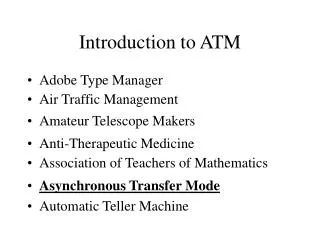
Introduction to ATM. Original: Susanne East seast@cisco.com. 1. Agenda. Introduction ATM Fundamentals Rudimentary ATM Concepts ATM Reference Model ATM Adaptation Layer (AAL) Traffic Management Campus ATM Internetworking. Characteristics of ATM. Voice. Data.

E N D
Introductionto ATM Original: Susanne East seast@cisco.com 1
Agenda • Introduction • ATM Fundamentals • Rudimentary ATM Concepts • ATM Reference Model • ATM Adaptation Layer (AAL) • Traffic Management • Campus ATM Internetworking
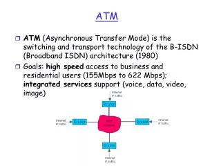
Characteristics of ATM Voice Data • Uses small, fixed-sized cells • Connection-oriented • Supports multiple service types • Applicable to LAN and WAN Cells Video
Creating Cells from Packets Dest.Address SourceAddress FrameCheck Packet Data Cells Header Payload Header Payload 5 ByteHeader Header Payload 53Bytes Header Payload 48 BytePayload ATM Cell
Campus Networking Evolution Traditional Network SharedEthernet Clients • Hierarchical design with broadcast control • 80/20 rule • Homogenous user communities • Moves, adds, and changes manually Corporate WAN and Internet LocalWorkgroupServers Cisco Systems Confidential 0680_03F7_c3 6
Campus Networking Evolution Contemporary Network SwitchedEthernetClients Ethernet Switchwith VLAN Support • Network hierarchy maintained • Traffic patterns migrating • Client and server performance increases • Moves, adds, and changes automated Corporate WAN and Internet Campus ATM Network Centralized High-Performance Servers ATM-Attached Station(s)
The Wonderful World of Acronyms AAL桝TM Adaptation Layer AAL1桽ee CBR AAL2桽ee VBR AAL3/4桽ee UBR AAL5桽ee ABR ABR桝vailable Bit Rate API桝pplication Programmer Interface B-ICI桞-ISDN Inter-Carrier Interface BUS桞roadcast and Unknown Server CAC桟onnection Admission Control CBR桟onstant Bit Rate CCITT桟onsultative Committee for International Telephony and Telegraph CDVT桟ell Delay Variation Tolerance CLP桟ell Loss Priority CLR桟ell Loss Ratio CS桟onvergence Sublayer EFCI桬xplicit Forward Congestion Indicator ELAN桬mulated LAN GCRA桮eneric Cell Rate Algorithm GFC桮eneric Flow Control HEC桯eader Error Check IISP桰nterim Inter-Switch Signaling Protocol ILMI桰nterim Local Management Interface
The Wonderful World of Acronyms IPD桰ntelligent Packet Discard LANE桳ocal Area Network Emulation LEC桳AN Emulation Client LES桳AN Emulation Server LECS桳AN Emulation Configuration Server LIS桳ogical IP Subnet MBS桵aximum Burst Size MCR桵inimum Cell Rate MCTD桵aximum Cell Transfer Delay MPC桵POA Client (aka Edge Device) MPOA桵ulti-Protocol Over ATM MPS桵POA Server (aka Router Server) NNI桸etwork-to-Network Interface OC桹ptical Carrier PCR桺eak Cell Rate PMD桺hysical Media Dependent PNNI桺rivate Network-to-Network Interface PTI桺ayload Type Identifier PVC桺ermanent Virtual Circuit Q.SAAL梐ka Q.2100桽ignaling ATM Adaptation Layer RFC1483桵ultiprotocol Encapsulation over AAL5 RFC1577桟lassical IP and ARP over ATM RM桼esource Management
The Wonderful World of Acronyms SAR桽egmentation and Reassembly SDH桽ynchronous Digital Hierarchy SONET桽ynchronous Optical Network STM桽ynchronous Transport Mode STS桽ynchronous Transport Signal SCR桽ustained Cell Rate SVC桽witched Virtual Circuit SSCOP桽ignaling Specific Convergence Protocol TC桾ransmission Convergence UBR桿nspecified Bit Rate UNI桿ser-to-Network Interface UPC桿sage Parameter Control VBR-NRT梀ariable Bit Rate-Non-Real Time VBR-RT梀ariable Bit Rate-Real Time VC梀irtual Circuit (or sometimes Virtual Connection) VCC梀irtual Channel Connection VCI梀irtual Channel Identifier VC Switch梀irtual Circuit Switch VP梀irtual Path VPC梀irtual Path Connection VPI梀irtual Circuit Identifier VP Switch梀irtual Path Switch VS/VD梀irtual Source/Virtual Destination
Agenda • Introduction • ATM Fundamentals • Rudimentary ATM Concepts • ATM Reference Model • ATM Adaptation Layer (AAL) • Traffic Management • Campus ATM Internetworking
Rudimentary ATM Concepts • Physical layer • Signaling • Cell format • Connection types
ATM Transmission Media ATM SDH/SONET Rates Chart SDH SONET Rate桵bps • CCITT (Consultative Committee for International Telephony and Telegraph) • ITU (International Telecommunications Union) STS-1/OC-1 51.84 STM-1 STS-3/OC-3 155.52 STM-4 STS-12/OC-12 622.08 STM-8 STS-24/OC-24 1,244.16 STM-16 STS-48/OC-48 2,488.32 Cisco Systems Confidential 0680_03F7_c3 13
ATM Physical Interface Rates Framing DataRate(Mbps) Media Multi-ModeFiber Single-ModeFiber CoaxialCable UTP? UTP? STP DS1E1J2DS3E3E4 1.5442.0486.234534139 (TP)(TP) X ATM25STS 1STS3c/STM1 25.651.8155 X STS 12c/STM44B/5B (TAXI)8B/10B(Fiberchannel) 622100155 = Standardized = Proposed/In Progress X
Rudimentary ATM Concepts • Physical layer • Signaling • Cell format • Connection types
ATM Building Blocks • ATM signaling • UNI and NNI • Virtual connections • VCC, VP, and VC
ATM Signaling Public UNIaka B-ICI Public ATM Network NNI • UNI = User-to-Network Interface • NNI = Network-to-Network Interface • Cell header content varies depending on who抯 talking to whom UNI NNI NNI Private ATM Network
Virtual Path and Virtual Channels Virtual Channels (VC) ATM Physical LinkVirtual Channel Connection (VCC) Virtual Path (VP) E3OC?2 Virtual Path (VP) Virtual Channels (VC) Virtual Channel(VC)Logical PathBetween ATM End Points Virtual Channel Connection(VCC)Contains Multiple VPs Virtual Path(VP)Contains Multiple VCs Connection Identifier = VPI/VCI Cisco Systems Confidential 0680_03F7_c3 18
2 1 3 ATM Switches Input Output 45 Port VPI/VCI Port VPI/VCI 1 29 2 45 29 64 • ATM switches translate VPI/VCI values • VPI/VCI value unique only per interface?eg: locally significant and may be re-used elsewhere in network 2 45 1 29 1 64 3 29 3 29 1 64 29
VP and VC Switching VC Switch VCI 1 VCI 2 VCI 3 VCI 4 Port 2 VPI 1 VPI 3 VPI 2 VP Switch VPI 2 Port 1 VCI 1 VPI 1 VPI 3 VCI 2 VCI 1 VPI 4 VPI 5 VCI 2 Port 3 Cisco Systems Confidential 0680_03F7_c3 20
Virtual Channels and Virtual Paths Virtual Channel Connection (VCC) • This hop-by-hop forwarding is known as cell relay Virtual PathConnection (VPC) UNI UNI NNI NNI VCSwitch VPSwitch VCSwitch VPI = 1VCI = 1 VPI = 2VCI = 44 VPI = 26VCI = 44 VPI = 20VCI = 30
Rudimentary ATM Concepts • Physical layer • Signaling • Cell format • Connection types
Creating Cells from Packets Dest.Address SourceAddress FrameCheck Packet Data Cells Header Payload Header Payload SARSegmentation and Reassembly Header Payload Header Payload Segmentation Happens at SourceReassembly Happens at Destination
ATM Cell Header 5 ByteHeader 53 Bytes 48 BytePayload ATM Cell
GFC (4) VPI (12) VPI (8) VCI (16) VCI (16) PTI CLP PTI CLP HEC HEC 48 BytePayload 48 BytePayload ATM UNI Cell ATM NNI Cell ATM Cell Header Details GFC Generic Flow ControlUNI Cells Only! VPI/VCI Identifies VirtualPaths and Channels PTI Payload Type Identifier3 Bits: 1. User/Control Data2. Congestion3. Last Cell CLP Cell Loss Priority Bit HEC Header Error Check8 Bit CRC
Rudimentary ATM Concepts • Physical layer • Signaling • Cell format • Connection types
ATM Connection Types • PVC • SVC • Soft PVC
S2 1 S6 1 1 S1 S8 S3 S5 2 2 S4 2 S7 Connection Types S2 S6 S1 S3 S5 S8 VC S4 S7 • Connectionless: Packet Routing • Path 1 = S1, S2, S6, S8 • Path 2 = S1, S4, S7, S8 • Data can take different pathand can arrive out of order • Connection Oriented: Cell Switching • VC = S1, S4, S7, S8 • Data takes the same path and arrives in sequence
A B Permanent Virtual Circuit (PVC) Input Output Input Output Port VPI/VCI Port VPI/VCI Port VPI/VCI Port VPI/VCI 1 29 3 45 1 33 3 02 2 52 4 15 2 15 3 14 29 1 64 3 29 1 64 3 29 • VPI/VCI tables in network equipment updated by administrator 3 29 1 64 3 29 1 64 1 15 4 2 C 45 2 3 3 14 30 43 3 16 2 Input Output Input Output 2 1 Port VPI/VCI Port VPI/VCI Port VPI/VCI Port VPI/VCI 4 1 45 2 16 1 16 2 43 10 2 52 1 29 3 14 4 10 D 1 64 3 29 1 64 3 29 3 29 1 64 3 29 1 64
A UNISignaling UNISignaling NNISignaling B Switched Virtual Circuit (SVC) Input Output Input Output Port VPI/VCI Port VPI/VCI Port VPI/VCI Port VPI/VCI 1 29 3 45 1 64 3 29 1 64 3 29 • Dynamically set up connectionsvia signaling 3 29 1 64 3 29 1 64 1 4 1 C 2 3 3 3 2 Input Output Input Output 2 1 Port VPI/VCI Port VPI/VCI Port VPI/VCI Port VPI/VCI 4 2 52 1 29 D 1 64 3 29 1 64 3 29 3 29 1 64 3 29 1 64
A UNISignaling UNISignaling NNISignaling B Switched Virtual Circuit (SVC) Input Output Input Output Port VPI/VCI Port VPI/VCI Port VPI/VCI Port VPI/VCI 1 29 3 45 1 29 3 45 1 64 3 29 1 64 3 29 • Transfer data over newly established link 3 29 1 64 3 29 1 64 1 4 1 C 2 3 3 3 2 Input Output Input Output 2 1 Port VPI/VCI Port VPI/VCI Port VPI/VCI Port VPI/VCI 4 1 45 2 16 1 16 2 43 2 52 1 29 D 1 64 3 29 1 64 3 29 3 29 1 64 3 29 1 64
UNISignaling UNISignaling NNISignaling B Switched Virtual Circuit (SVC) Input Output Input Output Port VPI/VCI Port VPI/VCI Port VPI/VCI Port VPI/VCI 1 29 3 45 1 64 3 29 1 64 3 29 A • Dynamically tear down connectionsvia signaling 3 29 1 64 3 29 1 64 1 4 1 C 2 3 3 3 2 Input Output Input Output 2 1 Port VPI/VCI Port VPI/VCI Port VPI/VCI Port VPI/VCI 4 2 52 1 29 D 1 64 3 29 1 64 3 29 3 29 1 64 3 29 1 64
UNISignaling UNISignaling NNISignaling B Soft PVC Input Output Input Output Port VPI/VCI Port VPI/VCI Port VPI/VCI Port VPI/VCI 1 29 3 45 1 29 3 45 1 64 3 29 1 64 3 29 • PVC established manually across UNI and dynamically across NNI A 3 29 1 64 3 29 1 64 1 C 3 1 Input Output Input Output 2 Port VPI/VCI Port VPI/VCI Port VPI/VCI Port VPI/VCI 1 16 2 43 2 52 1 29 D 1 64 3 29 1 64 3 29 3 29 1 64 3 29 1 64
Agenda • Introduction • ATM Fundamentals • Rudimentary ATM Concepts • ATM Reference Model • ATM Adaptation Layer (AAL) • Traffic Management • Campus ATM Internetworking
ATM Reference Model • Physical layer • ATM layer • ATM adaptation layer • A day in the life of a cell
ATM Reference Model ATM Adaptation Layer (AAL) ATM Layer Physical Layer
ATM Reference Model Physical Layer ATM Adaptation Layer (AAL) Two Sublayers: • Transmission Convergence (TC) • Framing • HEC • Physical Media Dependent (PMD) • Physical media coding ATM Layer Physical Layer
ATM Adaptation Layer (AAL) ATM Layer Physical Layer Physical Layer Framing DataRate(Mbps) Media Multi-ModeFiber Single-ModeFiber CoaxialCable UTP? UTP? STP DS1E1J2 1.5442.0486.23 (TP)(TP) DS3E3E4 4534139 X ATM25STS 1STS3c/STM1 25.651.8155 X STS 12c/STM44B/5B (TAXI)8B/10B(Fiberchannel) 622100155 = Standardized = Proposed/In Progress X
ATM Reference Model ATM Layer ATM Adaptation Layer (AAL) • Cell header insertion/removal • Cell Relay • Multiplexes/demultiplexes cells of different connections ATM Layer Physical Layer
ATM Layer Virtual Channel Connection (VCC) ATM Adaptation Layer (AAL) Virtual PathConnection (VPC) • Provides VPI/VCI values in header • Ensures that cells stay in the correct order UNI UNI ATM Layer NNI NNI VCSwitch VPSwitch VCSwitch Physical Layer VPI = 0VCI = 38 VPI = 12VCI = 44 VPI = 26VCI = 44 VPI = 0VCI = 36
ATM Reference Model ATM Adaption Layer (AAL) ATM Adaptation Layer (AAL) Two Sublayers: • Convergence Sublayer (CS) • Segmentation and Reassembly (SAR) ATM Layer Physical Layer
ATM Adaptation Layer (AAL) ATM Layer Physical Layer ATM Adaptation Layer桝AL AAL S A R AAL = QoS + SAR • CS梐ssigns different AAL抯/QoS for different traffic types • SAR梒ell <-> packet C S
ATM Adaptation Layer Class ServiceCategories Bit Rate ConnectionMode TimingConcern ApplicationExamples ATM Adaptation Layer (AAL) A AAL1 CBR(Constant) Connection-Oriented Yes • Bandwidth andthroughput guaranteed • Good for voice and video B AAL2 VBR(Variable)VBR-ATandVBR-NRT Connection-Oriented Yes • Best effort bandwidth and throughput • Good for live video,multimedia, LAN-to-LAN ATM Layer C AAL5 ABR(Available) Connection-Oriented No • Best effort withcongestion feedback • Reliable delivery of bursty traffic iflatency okay Physical Layer D AAL3/4 UBR(Un-specified) Connection-less No • No guarantee • For SMDS/LAN
ATM Reference Model • Physical layer • ATM layer • ATM adaptation layer • A day in the life of a cell
TCP Header App Data IP Header TCP Header App Data LLC IP Header TCP Header App Data QoS + LLC IP Header TCP Header App Data A Day in the Life of a Cell ATM Payload Processing TCP TCP Packet IP IP Datagram LLC/SNAP ConvergenceSublayer (CS) AAL Put in 48 Byte Cells桽AT into PDU SAR ATM Add 5 Byte Headers with VPI/VCI and CLP Transmission Convergence (STS, STM, DS) PHY Physical Media (MMF, SMF, STP, UDP,
ATM Switch ATM Layer Port 1 Port VPI VCI PHY ATM 1 2 37 2 1 51 Port 2 PHY ATM A Day in the Life of a Cell Traversing the Network AAL ATM PHY UNI VPI 2VCI 37 NNI ATM Switch ATM Layer Port 1 Port VPI VCI PHY ATM 1 1 51 2 3 39 VPI 3VCI 39 Port 2 AAL ATM PHY PHY ATM UNI Cisco Systems Confidential 0680_03F7_c3 46
Agenda • Introduction • ATM Fundamentals • Rudimentary ATM Concepts • ATM Reference Model • ATM Adaptation Layer (AAL) • Traffic Management • Campus ATM Internetworking
AAL • AAL criteria • Traffic parameters • QoS parameters • The AAL抯 • AAL1桟BR • AAL2梀BR • AAL3/4桿BR • AAL5桝BR
Contract AAL Criteria Contract ATM Network Contract • Traffic Parameters • Peak cell rate • Sustainable cell rate • Maximum burst size • Minimum Cell Rate • Quality of Service • Delay • Cell loss
AAL Criteria Traffic Parameters • Peak Cell RatePCR桵aximum data rate a connection can handle without losing data • Sustainable Cell Rate桽CRAverage ATM cell throughput the application is permitted • Maximum Burst Size桵BS桽ize of themaximum burst of contiguous cells that can be transmitted • Minimum Cell Rate桵CR桼ate of anapplication抯 ability to handle latency
AAL Criteria QoS桪elay • Maximum Cell Transfer DelayMCTD How long the network can take to transmit a cell from one endpoint to another • Cell Delay Variation Tolerance桟DVT Line distortion caused by change in interarrival times between cells aka jitter