Download

1 / 15
150 likes | 290 Views
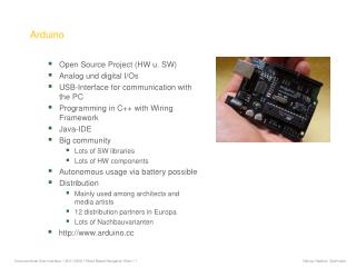
Arduino week3. 語法: 結構 實作: Analog in (VR 、光敏 + 七段顯示電壓 ) 簡報:廖崇義. 結構 for. f or() {}. 結構 while. while( val <1000) { digitalWrite (13,HIGH); }. 當條件 成立或為 1 時 執行大括弧內程式. 結構 do…while. Int val =2000; digitalWrite (13,LOW); do { digitalWrite (13,HIGH); } while ( val <1000 );

E N D
Arduino week3 語法:結構 實作:Analog in (VR、光敏+七段顯示電壓) 簡報:廖崇義
結構for • for() {}
結構while • while(val<1000) • { • digitalWrite(13,HIGH); • } 當條件成立或為1時 執行大括弧內程式
結構do…while • Intval=2000; • digitalWrite(13,LOW); • do • { • digitalWrite(13,HIGH); • } • while (val<1000); • digitalWrite(13,LOW);
結構break • break 離開for,while,do wile迴圈 • for (x = 0; x < 255; x ++) • { • val =analogRead(6); • if ( val< x) • { //當val小於x時pin13輸出LOW且離開for迴圈 • digitalWrite(13,LOW); • break; • } • digitalWrite(13,HIGH); • }
結構continue • for (x = 0; x < 255; x ++) • { • val=analogRead(6); • if ( val< x) • { //當val小於x時pin13輸出LOW且繼續for迴圈 • 下一個測試值 • digitalWrite(13,LOW); • continue; • } • digitalWrite(13,HIGH); • }
結構switch / case • switch (var) • { • case label: • // statements break; • case label: • // statements break; • default: • // statements • } • Label可以為int整數或char字元(ex.case ‘A’:)
analogRead() • analogRead(pin) • pin值為0~5對應ANALOG IN A0~A5 • 回傳值為0~1023,對應輸入電壓0~5V比例 • 取樣轉換時間為100 microseconds (0.1ms),每秒最高可取樣10000次 • 回傳值可用int變數存取 • Ex. intval; val = analogRead(1);
analogWrite()-PWM out • 頻率490 Hz • analogWrite(pin, value) • pin使用數位Port上有“ ~”標註的腳位 • 須事先使用pinMode將該腳為設為OUTPUT • value為設定方波HIGH的百分比(value/255) • value 值可設定範圍0-255 • Ex. val= analogRead(analogPin); // read the input pinanalogWrite(ledPin, val / 4); //val=0~1023
實作1.1VR+LED 將VR中間腳接到A3,另兩端一端接地一端接5V • intledPin = 9; // LED 一端接pin 9另一端接電阻再 接地 • intanalogPin = 3; // pin A3 類比輸入 • intval = 0; // 設val儲存類比取樣值 • void setup() • { • pinMode(ledPin, OUTPUT); // 設pin9為output • } • void loop() • { • val = analogRead(analogPin); // 類比取樣 • analogWrite(ledPin, val / 4); //使用pwm控制LED燈 • }
實作1.2VR+LED • intledPin = 9; // LED connected to digital pin 9 • intanalogPin = 3; // pin A3 類比輸入 • intval = 0; // 設val儲存類比取樣值 • void setup() • { • pinMode(ledPin, OUTPUT); // 設pin9為output • } • void loop() • { • val = analogRead(analogPin); // 類比取樣 • if(val<200) • val=200;//LED最小啟動功率 • if(val<20) • val=0;//避免VR零點雜訊 • analogWrite(ledPin, val / 4); //使用pwm控制LED燈 • }
照度視覺曲線 LED OUT 亮度 視覺曲線 修正曲線 PWM OUT
實作2.1光敏電阻調光 • 電路圖
實作2.2光敏+七段顯示電壓 • byte seven_disp[10][7] = { { 1,1,1,1,1,1,0 }, // = 0 • { 0,1,1,0,0,0,0 }, // = 1 • { 1,1,0,1,1,0,1 }, // = 2 • { 1,1,1,1,0,0,1 }, // = 3 • { 0,1,1,0,0,1,1 }, // = 4 • { 1,0,1,1,0,1,1 }, // = 5 • { 1,0,1,1,1,1,1 }, // = 6 • { 1,1,1,0,0,0,0 }, // = 7 • { 1,1,1,1,1,1,1 }, // = 8 • { 1,1,1,0,0,1,1 } }; // = 9 • inti=0,val=0; • void setup() • { • for(int x=2 ; x<9 ; x++) • pinMode( x, OUTPUT ); • } • void loop() • { • val = analogRead(3); • i=val/200; //可以改成i = map(val, 0, 1023, 0, 5); • for( int x=0 ; x<7 ; x++ ) • digitalWrite( x+2 , seven_disp[i][x] ) ; • delay(100); • }
map(value, fromLow, fromHigh, toLow, toHigh) • map()映射轉換一段數值,等比放大或縮小 • Ex. intval =(analogRead(3),0,1023,0,100) 將analogRead(3)取樣的值轉換成百分比 常用範例如: • 旋鈕控制伺服馬達角度intdeg=(analogRead(3),0,1023,0,180) • 超音波測距雷達intlongth=(analogRead(3),0,1023,0,280)