Download

1 / 142
1.42k likes | 1.66k Views
MPLS VPN TOI. eosborne@cisco.com. Agenda. How MPLS VPN works What Code Is MPLS VPN In? Platform Issues in Implementation Lab Demo - config. How MPLS-VPN Works. Concepts and goals Terminology Connection model Forwarding Mechanisms Topologies Scaling Configuration.

E N D
MPLS VPN TOI eosborne@cisco.com
Agenda • How MPLS VPN works • What Code Is MPLS VPN In? • Platform Issues in Implementation • Lab Demo - config
How MPLS-VPN Works • Concepts and goals • Terminology • Connection model • Forwarding • Mechanisms • Topologies • Scaling • Configuration
MPLS-VPN What is a VPN ? • An IP network infrastructure delivering private network services over a public infrastructure • Use a layer 3 backbone • Scalability, easy provisioning • Global as well as non-unique private address space • QoS • Controlled access • Easy configuration for customers
VPN Models - The Overlay model • Private trunks over a TELCO/SP shared infrastructure • Leased/Dialup lines • FR/ATM circuits • IP (GRE) tunnelling • Transparency between provider and customer networks • Optimal routing requires full mesh over over backbone
VPN Models - The Peer model • Both provider and customer network use same network protocol • CE and PE routers have a routing adjacency at each site • All provider routers hold the full routing information about all customer networks • Private addresses are not allowed • May use the virtual router capability • Multiple routing and forwarding tables based on Customer Networks
VPN Models - MPLS-VPN: The True Peer model • Same as Peer model BUT !!! • Provider Edge routers receive and hold routing information only about VPNs directly connected • Reduces the amount of routing information a PE router will store • Routing information is proportional to the number of VPNs a router is attached to • MPLS is used within the backbone to switch packets (no need of full routing)
Agenda • Concepts and goals • Terminology • Connection model • Forwarding • Mechanisms • Topologies • Scaling • Configuration
MPLS-VPN Terminology • Provider Network (P-Network) • The backbone under control of a Service Provider • Customer Network (C-Network) • Network under customer control • CE router • Customer Edge router. Part of the C-network and interfaces to a PE router
MPLS-VPN Terminology • Site • Set of (sub)networks part of the C-network and co-located • A site is connected to the VPN backbone through one or more PE/CE links • PE router • Provider Edge router. Part of the P-Network and interfaces to CE routers • P router • Provider (core) router, without knowledge of VPN
MPLS-VPN Terminology • Border router • Provider Edge router interfacing to other provider networks • Extended Community • BGP attribute used to identify a Route-origin, Route-target • Site of Origin Identifier (SOO) • 64 bits identifying routers where the route has been originated
MPLS-VPN Terminology • Route-Target • 64 bits identifying routers that should receive the route • Route Distinguisher • Attributes of each route used to uniquely identify prefixes among VPNs (64 bits) • VRF based (not VPN based) • VPN-IPv4 addresses • Address including the 64 bits Route Distinguisher and the 32 bits IP address
MPLS-VPN Terminology • VRF • VPN Routing and Forwarding Instance • Routing table and FIB table • Populated by routing protocol contexts • VPN-Aware network • A provider backbone where MPLS-VPN is deployed
Agenda • Concepts and goals • Terminology • Connection model • Forwarding • Mechanisms • Topologies • Scaling • Configuration
MPLS VPN Connection Model • A VPN is a collection of sites sharing a common routing information (routing table) • A site can be part of different VPNs • A VPN has to be seen as a community of interest (or Closed User Group) • Multiple Routing/Forwarding instances (VRF) on PE routers
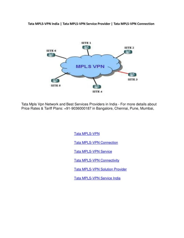
Site-4 Site-1 Site-2 Site-3 VPN-C VPN-A VPN-B MPLS VPN Connection Model • A site belonging to different VPNs may or MAY NOT be used as a transit point between VPNs • If two or more VPNs have a common site, address space must be unique among these VPNs
MPLS VPN Connection Model • The VPN backbone is composed by MPLS LSRs • PE routers (edge LSRs) • P routers (core LSRs) • PE routers are faced to CE routers and distribute VPN information through MP-BGP to other PE routers • VPN-IPv4 addresses, Extended Community, Label • P routers do not run BGP and do not have any VPN knowledge
VPN_A 10.2.0.0 CE VPN_B 10.2.0.0 PE CE VPN_A 11.6.0.0 CE PE VPN_B CE 10.1.0.0 MPLS VPN Connection Model iBGP sessions VPN_A 11.5.0.0 CE VPN_A 10.1.0.0 P P PE CE P P VPN_B PE CE 10.3.0.0 • P routers (LSRs) are in the core of the MPLS cloud • PE routers use MPLS with the core and plain IP with CE routers • P and PE routers share a common IGP • PE router are MP-iBGP fully meshed
CE PE CE Site-2 Site-1 MPLS VPN Connection Model • EBGP,OSPF, RIPv2,Static • PE and CE routers exchange routing information through: • EBGP, OSPF, RIPv2, Static routing • CE router run standard routing software
Site-2 Site-1 MPLS VPN Connection Model CE PE • EBGP,OSPF, RIPv2,Static CE • VPN Backbone IGP (OSPF, ISIS) • PE routers maintain separate routing tables • The global routing table • With all PE and P routesPopulated by the VPN backbone IGP (ISIS or OSPF) • VRF (VPN Routing and Forwarding) • Routing and Forwarding table associated with one or more directly connected sites (CEs) • VRF are associated to (sub/virtual/tunnel)interfaces • Interfaces may share the same VRF if the connected sites may share the same routing information
Site-2 Site-1 MPLS VPN Connection Model CE PE CE • Different site sharing the same routing information, may share the same VRF • Interfaces connecting these sites will use the same VRF • Sites belonging to the same VPN may share same VRF
Site-2 Site-1 MPLS VPN Connection Model CE PE • VPN Backbone IGP • EBGP,OSPF, RIPv2,Static CE • The routes the PE receives from CE routers are installed in the appropriate VRF • The routes the PE receives through the backbone IGP are installed in the global routing table • By using separate VRFs, addresses need NOT to be unique among VPNs
MPLS VPN Connection Model • The Global Routing Table is populated by IGP protocols. • In PE routers it may contain the BGP Internet routes (standard BGP-4 routes) • BGP-4 (IPv4) routes go into global routing table • MP-BGP (VPN-IPv4) routes go into VRFs
MPLS VPN Connection Model P P PE PE • VPN Backbone IGP P P iBGP session • PE and P routers share a common IGP (ISIS or OSPF) • PEs establish MP-iBGP sessions between them • PEs use MP-BGP to exchange routing information related to the connected sites and VPNs • VPN-IPv4 addresses, Extended Community, Label
MPLS VPN Connection ModelMP-BGP Update • VPN-IPV4 address • Route Distinguisher • 64 bits • Makes the IPv4 route globally unique • RD is configured in the PE for each VRF • RD may or may not be related to a site or a VPN • IPv4 address (32bits) • Extended Community attribute (64 bits) • Site of Origin (SOO): identifies the originating site • Route-target (RT): identifies the set of sites the route has to be advertised to
MPLS VPN Connection ModelMP-BGP Update • Any other standard BGP attribute • Local PreferenceMEDNext-hopAS_PATHStandard Community... • A Label identifying: • The outgoing interface • The VRF where a lookup has to be done (aggregate label) • The BGP label will be the second label in the label stack of packets travelling in the core
MPLS VPN Connection ModelMP-BGP Update - Extended community • BGP extended community attribute • Structured, to support multiple applications • 64 bits for increased range • General form • <16bits type>:<ASN>:<32 bit number> • Registered AS number • <16bits type>:<IP address>:<16 bit number> • Registered IP address
MPLS VPN Connection ModelMP-BGP Update - Extended community • The Extended Community is used to: • Identify one or more routers where the route has been originated (site) • Site of Origin (SOO) • Selects sites which should receive the route • Route-Target
MPLS VPN Connection ModelMP-BGP Update • The Label can be assigned only by the router which address is the Next-Hop attribute • PE routers re-write the Next-Hop with their own address (loopback interface address) • “Next-Hop-Self” BGP command towards iBGP neighborsLoopback addresses are advertised into the backbone IGP • PE addresses used as BGP Next-Hop must be uniquely known in the backbone IGP • No summarisation of loopback addresses in the core
Site-2 Site-1 MPLS VPN Connection Model VPN-IPv4 update is translated into IPv4 address (Net1) put into VRF green since RT=Green and advertised to CE-2 P P PE-2 PE-1 CE-2 • VPN Backbone IGP P P BGP,RIPv2 update for Net1,Next-Hop=CE-1 CE-1 VPN-IPv4 update:RD:Net1, Next-hop=PE-1SOO=Site1, RT=Green, Label=(intCE1) • PE routers receive IPv4 updates (EBGP, RIPv2, Static) • PE routers translate into VPN-IPv4 • Assign a SOO and RT based on configuration • Re-write Next-Hop attribute • Assign a label based on VRF and/or interface • Send MP-iBGP update to all PE neighbors
Site-2 Site-1 MPLS VPN Connection Model VPN-IPv4 update is translated into IPv4 address (Net1) put into VRF green since RT=Green and advertised to CE-2 P P PE-2 PE-1 CE-2 • VPN Backbone IGP BGP,OSPF, RIPv2 update for Net1Next-Hop=CE-1 P P CE-1 VPN-IPv4 update:RD:Net1, Next-hop=PE-1SOO=Site1, RT=Green, Label=(intCE1) • Receiving PEs translate to IPv4 • Insert the route into the VRF identified by the RT attribute (based on PE configuration) • The label associated to the VPN-IPv4 address will be set on packet forwarded towards the destination
MPLS VPN Connection Model • Route distribution to sites is driven by the Site of Origin (SOO) and Route-target attributes • BGP Extended Community attribute • A route is installed in the site VRF corresponding to the Route-target attribute • Driven by PE configuration • A PE which connects sites belonging to multiple VPNs will install the route into the site VRF if the Route-target attribute contains one or more VPNs to which the site is associated
Agenda • Concepts and goals • Terminology • Connection model • Forwarding • Mechanisms • Topologies • Scaling • Configuration
MPLS ForwardingPacket forwarding • PE and P routers have BGP next-hop reachability through the backbone IGP • Labels are distributed through LDP (hop-by-hop) corresponding to BGP Next-Hops • Label Stack is used for packet forwarding • Top label indicates BGP Next-Hop (interior label) • Second level label indicates outgoing interface or VRF (exterior label)
MPLS ForwardingPacket forwarding • MPLS nodes forward packets based on the top label • P routers do not have BGP (nor VPN) knowledge • No VPN routing information • No Internet routing information
MPLS ForwardingPenultimate Hop Popping • The upstream LDP peer of the BGP next-hop (PE router) will pop the first level label • The penultimate hop will pop the label • Requested through LDP • The egress PE router will forward the packet based on the second level label which gives the outgoing interface (and VPN)
PE2 receives the packets with the label corresponding to the outgoing interface (VRF) One single lookup Label is popped and packet sent to IP neighbor P routers switch the packets based on the IGP label (label on top of the stack) Penultimate Hop Popping P2 is the penultimate hop for the BGP next-hop P2 remove the top label This has been requested through LDP by PE2 IP packet IGP Label(PE2)VPN Label IGP Label(PE2)VPN Label IP packet IP packet IP packet VPN Label IP packet PE1 receives IP packet Lookup is done on site VRF BGP route with Next-Hop and Label is found BGP next-hop (PE2) is reachable through IGP route with associated label MPLS ForwardingMPLS Forwarding - Penultimate Hop Popping CE1 PE1 CE2 P1 P2 PE2 CE3
VPN_A 10.2.0.0 CE VPN_B 10.2.0.0 PE2 CE VPN_A 11.6.0.0 Data CE PE1 VPN_B CE 10.1.0.0 MPLS VPN Forwarding VPN_A 11.5.0.0 CE VPN_A P P 10.1.0.0 PE CE T8T2 Data P P VPN_B CE 10.3.0.0 <RD_B,10.1> , iBGP next hop PE1 <RD_B,10.2> , iBGP next hop PE2 <RD_B,10.3> , iBGP next hop PE3 <RD_A,11.6> , iBGP next hop PE1 <RD_A,10.1> , iBGP next hop PE4 <RD_A,10.4> , iBGP next hop PE4 <RD_A,10.2> , iBGP next hop PE2 <RD_B,10.2> , iBGP NH= PE2 , T2 T8 T1 T7 T2 T8 T3 T9 T4 T7 T5 TB T6TB T7 T8 • Ingress PE receives normal IP Packets from CE router • PE router does “IP Longest Match” from VPN_B FIB , find iBGP next hop PE2 and impose a stack of labels: exterior Label T2+ Interior LabelT8
VPN_A 10.2.0.0 CE VPN_B T2 Data 10.2.0.0 PE2 CE VPN_A 11.6.0.0 CE PE1 VPN_B CE 10.1.0.0 MPLS VPN Forwarding VPN_A 11.5.0.0 CE Data T2 Data TB VPN_A P P 10.1.0.0 PE CE TAT2 Data T8 T2 Data P P VPN_B CE 10.3.0.0 in / out T7 T8 T9 Ta Tb Tu Tw Tx Ty Tz T8,TA • All Subsequent P routers do switch the packet Solely on Interior Label • Egress PE router, removes Interior Label • Egress PE uses Exterior Label to select which VPN/CEto forward the packet to. • Exterior Label is removed and packet routed to CE router
Agenda • Concepts and goals • Terminology • Connection model • Forwarding • Mechanisms • Topologies • Scaling • Configuration
MPLS VPN mechanismsVRF and Multiple Routing Instances • VRF: VPN Routing and Forwarding Instance • VRF Routing Protocol Context • VRF Routing Tables • VRF CEF Forwarding Tables
MPLS VPN mechanismsVRF and Multiple Routing Instances • VPN aware Routing Protocols • Select/Install routes in appropriate routing table • Per-instance router variables • Not necessarily per-instance routing processes • eBGP, OSPF, RIPv2, Static
MPLS VPN mechanismsVRF and Multiple Routing Instances • VRF Routing table contains routes which should be available to a particular set of sites • Analogous to standard IOS routing table, supports the same set of mechanisms • Interfaces (sites) are assigned to VRFs • One VRF per interface (sub-interface, tunnel or virtual-template) • Possible many interfaces per VRF
Static BGP RIP Routing processes Routing contexts VRF Routing tables VRF Forwarding tables MPLS VPN mechanismsVRF and Multiple Routing Instances • Routing processes run within specific routing contexts • Populate specific VPN routing table and FIBs (VRF) • Interfaces are assigned to VRFs
Site-1 Site-2 Site-4 Site-3 Site-1 Site-2 Site-3 Site-4 VPN-C VPN-A VPN-B MPLS VPN mechanismsVRF and Multiple Routing Instances Logical view Multihop MP-iBGP P P Routing view PE PE VRFfor site-1 Site-1 routesSite-2 routes VRFfor site-2 Site-1 routesSite-2 routesSite-3 routes VRFfor site-3 Site-2 routesSite-3routesSite-4 routes VRFfor site-4 Site-3 routesSite-4 routes
Agenda • Concepts and goals • Terminology • Connection model • Forwarding • Mechanisms • Topologies • Scaling • BGP-4 Enhancements • Cap. Negotiation, MPLS, Route Refresh, ORF • Configuration
VPN_A 10.2.0.0 CE VPN_B 10.2.0.0 PE CE VPN_A 11.6.0.0 CE PE VPN_B CE 10.1.0.0 MPLS VPN Topologies iBGP sessions VPN_A 11.5.0.0 CE VPN_A 10.1.0.0 P P PE CE P P VPN_B PE CE 10.3.0.0 • VPN-IPv4 address are propagated together with the associated label in BGP Multiprotocol extension • Extended Community attribute (route-target) is associated to each VPN-IPv4 address, to populate the site VRF
MPLS VPN TopologiesVPN sites with optimal intra-VPN routing • Each site has full routing knowledge of all other sites (of same VPN) • Each CE announces his own address space • MP-BGP VPN-IPv4 updates are propagated between PEs • Routing is optimal in the backbone • Each route has the BGP Next-Hop closest to the destination • No site is used as central point for connectivity
Site-3 N3 Site-1 EBGP/RIP/Static N2,NH=CE2 MPLS VPN TopologiesVPN sites with optimal intra-VPN routing EBGP/RIP/Static N3NH=CE3 Routing Table on CE3 N1, PE3N2, PE3N3, Local VRFfor site-3 N1,NH=PE1N2,NH=PE2N3,NH=CE3 IntCE3 PE3 VPN-IPv4 updates exchanged between PEs RD:N1, NH=PE1,Label=IntCE1, RT=BlueRD:N2, NH=PE2,Label=IntCE2, RT=BlueRD:N3, NH=PE3,Label=IntCE3, RT=Blue PE1 IntCE2 VRFfor site-1 N1,NH=CE1N2,NH=PE2N3,NH=PE3 VRFfor site-2 N1,NH=PE1N2,NH=CE2N3,NH=PE3 Site-2 PE2 N2 IntCE1 Routing Table on CE2 N1,NH=PE2N2,LocalN3,NH=PE2 EBGP/RIP/Static Routing Table on CE1 N1, LocalN2, PE1N3, PE1 N1NH=CE1 N1
MPLS VPN TopologiesVPN sites with Hub & Spoke routing • One central site has full routing knowledge of all other sites (of same VPN) • Hub-Site • Other sites will send traffic to Hub-Site for any destination • Spoke-Sites • Hub-Site is the central transit point between Spoke-Sites • Use of central services at Hub-Site