Download
1 / 22
230 likes | 401 Views
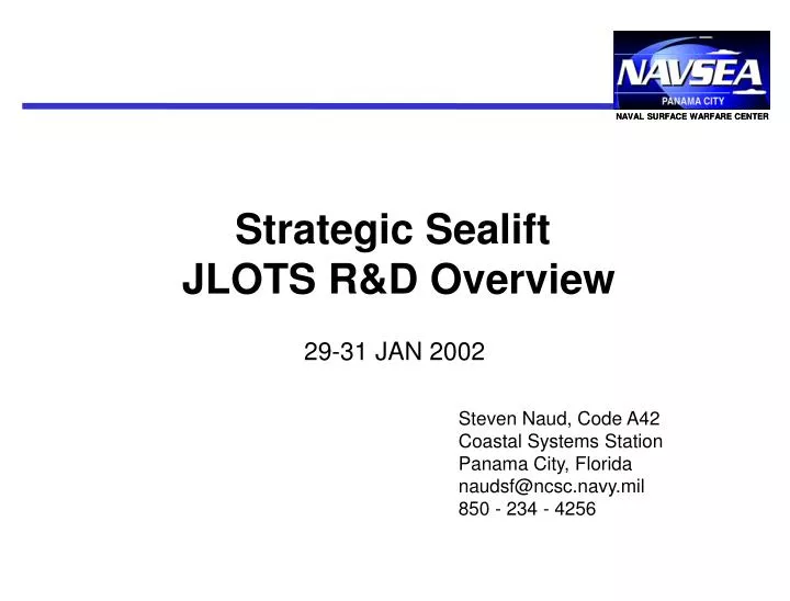
NAVAL SURFACE WARFARE CENTER. Strategic Sealift JLOTS R&D Overview. 29-31 JAN 2002. Steven Naud, Code A42 Coastal Systems Station Panama City, Florida naudsf@ncsc.navy.mil 850 - 234 - 4256. NAVAL SURFACE WARFARE CENTER. Strategic Sealift JLOTS R&D Overview. CSS R&D Topics:

E N D
NAVAL SURFACE WARFARE CENTER Strategic Sealift JLOTS R&D Overview 29-31 JAN 2002 Steven Naud, Code A42 Coastal Systems Station Panama City, Florida naudsf@ncsc.navy.mil 850 - 234 - 4256
NAVAL SURFACE WARFARE CENTER Strategic Sealift JLOTS R&D Overview • CSS R&D Topics: • Ship Roll Mitigation System (SRMS) • T-ACS/Containership Interface (TCI) • Ship Attached RIB Section (SARS)
Ship Roll Mitigation System (SMRS) OBJECTIVE: Investigate the Ship Roll Stimulator concept to determine if controls can be adapted to mitigate ship roll through repeated system operation in opposition to wave caused ship motion PAYOFF Prove the feasibility of reducing ship motion from swells while at anchor during JLOTS cargo operations, while using technology developed under the current Sea State 3 Crane ATD. • STATUS/PLANS: JAN02 • Initial study by Old Dominion University completed. • Plan to verify control methodology with SRSS 1/8th scale and/or simulation models. • Will modify full scale SRSS controls and test once ATD is completed
T-ACS/Containership Interface (TCI) OBJECTIVE: Investigate geometry of T-ACS & Post-Panamax containerships (PPC) in sea-state-three to determine compatibility during offload. Investigate current fendering and mooring system to verify SS-3 capability and identify any improvements. PAYOFF: Development of hardware and/or procedures to improve mooring and operation of T-ACS, especially with larger Post-Panamax sized containerships. • STATUS/PLANS: JAN02 • Study completed by both NSWC-CD (fendering) and NSWC-DD/CSS (geometry). • Plan to complete documentation. • Pursue development of Vacuum Mooring.
NAVAL SURFACE WARFARE CENTER ) ) 3o 5o ( 3o T-ACS/Containership Interface (TCI) ? Simulated hull outline for SOVEREIGN MAERSK Possible impact at low boom angles when adding heave & pitch to roll motion. PPC T-ACS ? T-ACS Superstructure may impact PPC hull when sway and yaw is included w/ roll. • Geometry Study Found Interface Problems: • RBTS arms can conflict with PPC hull structure or container stack starting with a relative 3.5 degree combined roll angle from both the T-ACS and Post-Panamax Containership (PPC). • T-ACS superstructure can impact PPC hull or container stack starting with about 8 degrees of combined roll • Crane boom can reach and remove cargo from PPC centerline, but boom clearance w/r PPC hull may not be adequate when operating with swell induced heave, pitch and roll. Must review limits on a case by case basis for specific PPC hull and loadout. x RBTS arms will impact hull at 3.5o of combined roll.
T-ACS/Containership Interface (TCI) • Mooring & Fendering Study: • Review of current fendering operations show that procedures work well for SS-3, however swell can cause excessive motions in one or both ships. Recommendations include: • Ship heading control by using stern anchors or tugs to orient both ships for minimizing motion • Improve mooring lines for greater resilience and strength. • Develop more robust fenders to reduce damage • Geometric study shows that size and position of fenders do not prevent impacts between the two ships. • Current methods are passive restraints only, where fenders work only in compression and mooring lines only in tension. • Potential Solution: • Strait Mooring International & Mooring International, Ltd., evaluated the TCI problem • Vacuum mooring concept for ship-to-ship mooring is recommended to provide: • Semi-rigid restraint to mitigate relative ship motions in both tension and compression • Mooring position can be elevated to provide increased protection of superstructures • Develop automated fendering to reduce manpower and time required for mooring/releasing the two ships and improve overall safety in heavier seas.
T-ACS/Containership Interface (TCI) Vacuum Mooring by Mooring International, Ltd.
T-ACS/Containership Interface (TCI) By Mooring International, Ltd.
RIBS Section Short RIBS Section SHIP ATTACHED RIB SECTION (SARS) OBJECTIVE: Utilize the Army’s Rapidly Installable Breakwater technology with minimal modifications and in combination with sealift ships to form a cost effective breakwater during JLOTS operations. PAYOFF Outline a ship deployable breakwater concept for reducing lighter motion during JLOTS cargo operations, while using technology being developed by the Army’s RIB program.
SHIP ATTACHED RIB SECTION (SARS) • SARS Topics: • CSS Ship/RIB Interaction Model • SMI/MIL Mooring Study • CSC Vessel Motion Analysis
SHIP ATTACHED RIB SECTION (SARS) • CSS Ship/RIB Interaction Model: • Modeling performed on visualNastran Motion 2001 (formerly Working Model) to analyze the dynamic forces of mooring SARS • Only one case modeled due to personnel constraints • Ship model based on T-ACS 5 • 200 foot long RIB section attached at 60 degrees relative to ship centerline at one end • T-ACS anchored at two points with elastic lines similar to nylon • RIB moored with three lines (one to ship and two to anchors) • Wave direction - perpendicular to T-ACS • SS-3 was simulated as buoyancy or wave current drag forces on T-ACS and RIB section using a 5 ft sinusoid with a 7.5 second period in vertical and athwartship directions • No current in this simulation
SHIP ATTACHED RIB SECTION (SARS) • Modeling Results: • Overall RIB motion appears realistic, but needs validation • Peak mooring reaction forces between ship and RIB ranging from 50 to 90 Klb. • Aft anchor line on RIB has line tension peaks ranging from 10 to 40 Klb.
Sample SARS Simulation Page Anchor Line Direction of Waves (Sea-State 3) 90o Constraint 50 & Tension Results Calm Zone T-ACS Ship Constraint 712 & Tension Results RIB Section Anchor Line 60o
SHIP ATTACHED RIB SECTION (SARS) SARS Simulation(play speed approx. real time)
SHIP ATTACHED RIB SECTION (SARS) • SMI/MIL Mooring Study: • Mooring analysis of SARS mooring options completed by Strait Mooring International, USA, and Mooring International, Ltd. • Three concepts generated • Helical mooring of T-ACS and RIB for adjustable positioning • Recommended development of helical drill rig for emplacement • Semi-dynamic positioning with only single point mooring • Fully dynamic positioning of RIB • Large SeaFlex line (> 20 Klb.) not yet available to handle peak loads • May not be necessary depending on validation of live loads and mooring requirements • May provide means of reducing helical mooring field by allowing short scopes
SHIP ATTACHED RIB SECTION (SARS) • For maximum RIB effectiveness, T-ACS (or LMSR) should be positioned to minimize ship motion while providing a protective lee. • When properly emplaced, helical anchors provide a more secure hold than normal embedment anchors. • Helical emplacement could use a remotely operated drill rig as conceptualized above. • Coupled with a high strength SeaFlex mooring line (to be developed), short scopes of 2:1 are possible, thereby reducing size of mooring field.
SHIP ATTACHED RIB SECTION (SARS) By Strait Mooring International
SHIP ATTACHED RIB SECTION (SARS) SEMI-DYNAMIC POSITIONING WITH 1 TUG • To avoid the complexity of laying out a mooring field of helicals and the potential for anchor line interference with the containership, a mooring concept is to dynamically position the outside end of the RIB section using a lighter, tug or other suitable, small vessel. • RIB effectiveness will be lost unless the T-ACS vessel can also maintain its position to provide a lee, and will require its own dynamic positioning.
SHIP ATTACHED RIB SECTION (SARS) FULL DYNAMIC POSITIONING WITH 2 TUGS • To eliminate the potentially high stresses occurring between the mooring of two large inertial masses (i.e. ship with RIB section) • Concept is to dynamically position both ends of the RIB section using two small vessels. • Combination of current and weather may make the coordinated positioning of the RIB difficult to maintain.
SHIP ATTACHED RIB SECTION (SARS) • CSC Vessel Motion Analysis: • CSC, Advanced Marine, completed vessel motion analysis for various orientations of wind driven waves and swell combined into a sea-state 3 (SS-3) environment • The maximum relative and absolute motions, velocities, and accelerations of the vessels were computed with 95% confidence. • The significant waveheight was 5.0 ft in all calculations. • Initial baseline calculations were carried out in each spectrum individually, at 9 wind driven and 9 swell wave headings, using significant waveheights of 5 ft. • Calculations were performed for all 81 combinations of sea and swell headings and presented in a 3D Excel file.
SHIP ATTACHED RIB SECTION (SARS) • Recommendations: • CSS Ship/RIB Interaction Model: • Modeling should be refined and validated with data from XM01 and other exercises • SMI/MIL Mooring Study: • Determine if a single RIB can be effectively moored to a T-ACS or LMSR • If ship attached mooring is not used, then availability of suitable assets for dynamically positioning the RIB section should be assessed • Plan to evaluate concepts further to determine viability for shipboard operations/deployment • CSC Vessel Motion Analysis • Fund CSC, Advanced Marine to refine motion analysis to allow variations for both swell and wave height, and changes to each of the modal periods • Review motion analysis to determine nominal mooring configuration for T-ACS • Plan to find multi-point mooring orientation(s) that minimizes T-ACS motion and maximizes the benefit of creating a lee with the help of SARS • Use RIB to extend range of calm region by removing wave diffraction around bow and/or stern for easing lighter approach & mooring • May find there is no best multi-point mooring position for T-ACS due to variability of seas (Ship Roll Mitigation System???)
SHIP ATTACHED RIB SECTION (SARS) • Summary: • SARS configuration is indeterminate and depends on the following: • Verifying that the dynamic mooring forces are manageable • Finding a set of T-ACS mooring positions that will provide moderate ship motions and maintain a lee • Developing an effective method to deploy and moor SARS