Download
1 / 35
370 likes | 466 Views
PHYSICAL METHODS. ** Suitable for comparatively less reactive metals. ** Pure metal and alloy powders ATOMIZATION: “The break up of a liquid metal into fine droplets, typically smaller than 150 μ m.”

E N D
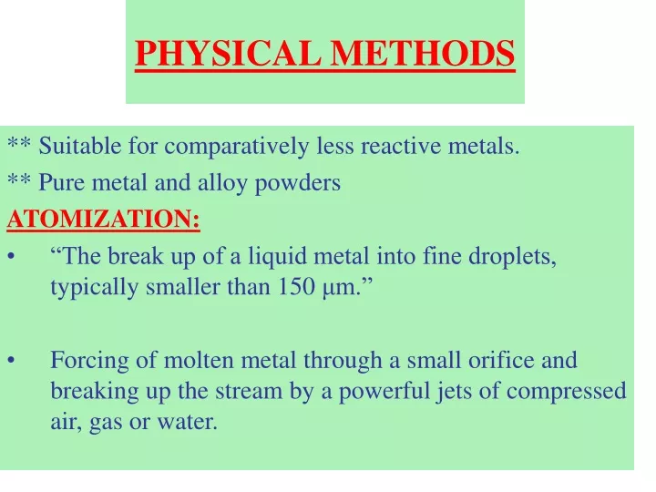
PHYSICAL METHODS ** Suitable for comparatively less reactive metals. ** Pure metal and alloy powders ATOMIZATION: “The break up of a liquid metal into fine droplets, typically smaller than 150 μm.” Forcing of molten metal through a small orifice and breaking up the stream by a powerful jets of compressed air, gas or water.
Types of Atomization: a) On the basis of atomization media; i) Gas atomization and ii) Water atomization • On the basis of kind of energy being used; i) Centrifugal atomization ii) Vacuum atomization iii) Plasma atomization iv) Ultrasonic atomization
Mechanism of Atomization: • Four stages 1st Stage: The impingement of high velocity jets of water or gas produce sinuous waves which cause disturbance in the liquid sheet. 2nd Stage: Wave fragments and ligaments formation through shearing forces is produced by the disturbance at stage one.
3rd Stage: • Breakdown of ligaments into droplets ----- primary atomization. • Regular particle shape --- high surface tension & low cooling rate. • Irregular particle shape --- low surface tension & high cooling rate. 4th Stage: • Further deformation and thinning of droplets and wave fragments into smaller particles occur --- secondary atomization. • Size reduction is limited by melt viscosity, temperature and acceleration force.
Model for the disintegration of a liquid sheet by a high-velocity gas jet.
GAS ATOMIZATION: The breakup of liquid metal stream into droplets by the impingement of high pressure gas. OR The liquid metal stream is disintegrated by rapid gas expansion out of a nozzle. Air, nitrogen, helium or argon The major components of a typical installation include: A melting furnace facility An atomization chamber usually 5 – 6 m high A gas jet compressor net-work.
The powder characteristics and its overall morphology depends on the following variables. • Degree of super heat • Size of stream • Force to disintegrate the stream/ pressure of gas • Viscosity of the molten metal • Nozzle diameter
Fine particle size is favored by: • High pressure of the gas/atomization fluid • Low metal viscosity • Low metal surface tension • Degree of superheat • Small nozzle diameter • Short metal stream • Short jet length
Figure: Scanning electron microscopy of 316L stainless steel gas-atomized powder.
WATER ATOMIZATION: • m.p below 1500 oC • Less reactive metals • Atomization tank --- slightly smaller in height as compared to Gas Atomization Tank. • Water is directed by a single jet, multiple jets or annular ring around the bottom nozzle of tundish. • Rapid quenching • Pressure of water is important • Water has low compressibility and higher density than gas, hence the distance of the impact and the metal exit from the nozzle play less role.
Powder shape ------- irregular • Surface texture ---- rough with some oxidation. (relatively high surface oxygen contents) • High volume and low cost production • Microstructural characteristics ---- amorphous to fine crystalline and dendritic. • Glass forming additive (boron etc) also favors the appearance of amorphous structure.
The major components of a typical installation include; • a melting facility • A tundish, a reservoir that supplies a uniform and controlled flow of molten metal to the tundish nozzle • an atomizing chamber • powder drying equipment
VACUUM ATOMIZATION • When the molten metal supersaturated with gas under pressure is suddenly exposed to vacuum, the gas expands, comes out of the solution and causes liquid metal to be atomized. • Vacuum atomizing unit consists of two main sections; • Lower chamber is the vacuum induction furnace for melting. • Upper one is atomization chamber with powder collection chamber. **Both chambers are vertical. • Metals and alloys are melted
Molten metal is saturated with soluble and non-reactive gas. • The molten metal stream is atomized by introducing gas-saturated stream through a ceramic transfer tube and nozzle in a reduced pressure (vacuum) chamber. • Also called “melt-explosion technique” because the high pressure stream and gas de-saturation cause the melt to literally explode into the vacuum chamber. • The collection chamber is designed to maximize the yield, minimize contamination, and ease of cleaning. • Powder handling ----- under inert gas or vacuum. • Powder produced is spherical, clean and of a high purity. • High cooling rate --- microcrystalline structure.
ROLLER ATOMIZATION • Uses a high velocity rolling mill to quickly break up the melt stream • High cooling rate ------ amorphous metals • Powder is flake shaped
ROTATING DISC ATOMIZATION • Involves the impinging of a stream of molten metal onto the surface of a rapidly spinning disk. • The liquid metal is mechanically atomized and thrown off the edges of the spinning disks. • Generally, spherical & coarse powder • Low melting metals • In some cases, the disintegration of the droplets occurs after exit from the rotating disc slit. • Control of the opening size, provides some control of the droplet size.
ROTATING DISC ATOMIZATION • Coarse powder • Low melting metals • Control of the opening size, provides some control of the droplet size. • The disintegration of the droplet occurs after exit from the rotating disc slit.
PLASMA ATOMIZATION • Wire, rod or bar is fed into a plasma torch where melting and rapid acceleration of particles occurs. • As a result of this rotation a fine powder is sprayed out of the torch. • If the powder is provided a long flight path, a spherical shaped powder results.
Rapid Solidification Process • RSP cools liquid metal at a rate of 106 °C /sec or higher. • Such a high cooling rate does not permit movement (diffusion) of atoms in the material being quenched. • The atoms are unable to occupy the equilibrium crystal sites that they normally do in the conventional methods. • Very thin ribbons are produced by melt spinning process when a jet of liquid metal is extruded through a round orifice impinging on the outer rim of rotated chilled block.
These ribbons are continuous, several millimeter wide and 25-50 um (micron) thick. • This thin ribbon produced is milled in a pulverizer to produce a powder of the metal and the size of the powder is controlled by milling parameters as well as the ribbon thickness.
Rotating Electrode Process • The end of a metal bar or rod is melted while it is rotated about its longitudinal axis. • Molten metal produces droplets which by centrifugal force are ejected away from the center and solidify as spherical powder particles. • It consists of a large diameter (more than 2 meter) tank mounted in vertical position. • The consumable rotating electrode is fed through sealed assembly in horizontal position located in the central axis of the tank. • This electrode is an anode of D.C. power supply.
While non-melted permanent cathode may be a tungsten tipped device provided with adequate cooling. • Usually, melting is conducted under inert gas; the preferred medium is helium, which offers improved heat transfer properties and arc characteristics. • This technique is used for short bar and long bar electrodes.
In short bar apparatus a consumable electrode of 90 mm in diameter 200-250 mm in length is used. • The anode is held in a collet of a precision spindle, the head of the spindle is projected into the tank through a fast rotating seal mechanism. • Electrode stub, removal and the introduction of new electrodes to the collet is done manually via a glove transfer port which is located in front of the machine adjacent to the cathode. • Short bar methodology is appropriate for converting experimental quantities of materials specifically alloys that are inherently brittle, or materials that have low specific stiffness where an electrode of long aspect ratio is not practical.
Long bar apparatus is used to consume 60-65mm diameter and 1500- 1800 mm (length) electrodes. • In this machine a precision spindle is mounted on a table that carries electrical drive mechanism outside the tank. • The table moves towards the tank axially feeding the rotating electrode through special seal and bearing assembly. • The rotation rate for long bar assembly is 1570 radians/ sec (15000 rpm). This rate is variable and is controlled by the machine operator who has to control the particle size and shape of the powder.
The particle size is also dependent upon the surface tension of metal, electrode diameter and rotation rate. • The shape of the particles is mostly spherical. • Powders for photo-copying machines are being produced by this technique. • Titanium and its alloys are being powdered by this method to suit it for near net shape compaction. • Because this technique prevents contact of molten alloy or metal with any container material, hence the powder is produced with cleanliness.