Download
1 / 35
420 likes | 683 Views
Single Area OSPF Concepts. OSPF Basics. OSPF versus RIP. Open Shortest Path First (OSPF), like RIP, is based on “Open” standards. RFC 2328 OSPF is often preferred over RIP because of its scalability. It can be configured on smaller networks using one “Area” (shown in yellow)

E N D
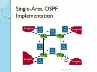
OSPF versus RIP • Open Shortest Path First (OSPF), like RIP, is based on “Open” standards. • RFC 2328 • OSPF is often preferred over RIP because of its scalability. • It can be configured on smaller networks using one “Area” (shown in yellow) • Or scaled to larger networks with virtual no limit. • Networks and Areas are easily added or removed • VLSM and Route Summaries are fully supported.
OSPF versus RIP • Open Shortest Path First (OSPF), like RIP, is based on “Open” standards. • RFC 2328 • OSPF is often preferred over RIP because of its scalability. • It can be configured on smaller networks using one “Area” (shown in yellow). • Or scaled to larger networks with virtually no limit. • Networks and Areas are easily added or removed, • VLSM and Route Summaries are fully supported.
OSPF versus RIP • Open Shortest Path First (OSPF), like RIP, is based on “Open” standards. • RFC 2328 • OSPF is often preferred over RIP because of its scalability. • It can be configured on smaller networks using one “Area” (shown in yellow). • Or scaled to larger networks with virtually no limit. • Networks and Areas are easily added or removed. • VLSM and Route Summaries are fully supported.
OSPF versus RIP • Open Shortest Path First (OSPF), like RIP, is based on “Open” standards. • RFC 2328 • OSPF is often preferred over RIP because of its scalability. • It can be configured on smaller networks using one “Area” (shown in yellow). • Or scaled to larger networks with virtually no limit. • Networks and Areas are easily added or removed. • VLSM and Route Summaries are fully supported. 172.16.4.0/22 172.16.8.0/22 172.16.0.0/22 172.16.0.0/19 172.16.0.0/16 172.16.64.0/19 172.16.32.0/19 172.16.72.0/22 172.16.40.0/22 172.16.64.0/22 172.16.32.0/22 172.16.68.0/22 172.16.36.0/22
OSPF versus RIP • Speed of Convergence • RIP broadcasts every 30 seconds
OSPF versus RIP • Speed of Convergence • OSPF is event-driven. • Only changes are flooded to other routers. • Sends an LSA when a change occurs.
OSPF versus RIP • Path Selection • RIP can pick suboptimal paths because only hops are considered. • OSPF calculates the “Cost” of each link, which defaults to bandwidth (108/bps).
Because OSPF has superior convergence and path selection, it has a lower AD than RIP. Remember: AD is a measure of a route source’s “trustworthiness” or “believability” Administrative Distance
OSPF Terminology • Links—networks a router knows about; each router interface is a “link”. • Area—a group of routers identified with a unique ID; all routers in the same area share the same link-state database. • Cost—is the bandwidth of the media; can be manually configured. • SPF Algorithm (Dijkstra)—calculated by each router to choose the lowest-cost path. • Link-state—is a link “up” or “down”? • LSA—a link state advertisement. • Adjacencies Database—keeps track of all directly connected routers (also called neighbors). • Link-State Database—also known as the Topology database; picture of who is connected to what; all routers should have the same L-S DB. • Forwarding Database—known as the Routing table where the lowest-cost paths are installed. • Designated Router/Backup Designated Router (DR/BDR)— routers that are elected on multiaccess networks to be the focal point for routing updates.
OSPF Packet Types • OSPF uses a variety of packets to communicate with neighbors and the DR/BDR. • Type 1: Hello; a 64-byte packet sent at regular intervals to keep a link “alive”. • Type 2: DBD (Database Description); summary contents of a router’s link-state database sent to a newly discovered neighbor. • Type 3: LSR (Link-State Request); requests more specific information about a link from a neighbor’s link-state database. • Type 4: LSU (Link-State Update); transports LSAs to neighbor routers; for example, a reply to an LSR. • Type 5: LSAck (Link-State Acknowledgement); acknowledges receipt of an LSA; OSPF’s routing updates are connection-oriented.
OSPF Packet Header (All Types) • Below is the 20 byte packet header appended to the front of all OSPF packets. • Version specifies OSPF version; routers must be running the same version or adjacency with neighbors cannot be established. • Type specifies packet type (Type 1, Type2, etc.) • Packet Length is the length of the entire OSPF packet in bytes, including the standard OSPF packet header. • Router ID is the IP identity of the router who is originating the packet. • Area ID is the OSPF area that the packet is being sent into. • Authentication, if configured, is specified.
Hello Packet Header (Type 1) • Below is the additional fields added to the OSPF packet header to make an OSPF Hello packet header. • Network Mask is the number of bits turned on in the Subnet mask used by the sending router’s Router ID. • Hello Interval is number of seconds between sending router’s hellos • 10 sec. or 30 sec., depending on network type
Hello Packet Header (Type 1) • Options are described in Section A.2 of RFC 2328 • Router Priority is used for DR/BDR Elections. If set to 0, sending router is ineligible to become Designated Router. • Dead Interval is the number of seconds before sending router will consider a silent neighbor to be down. • Defaults to 4 times the Hello Interval
Hello Packet Header (Type 1) • Designated Router is the Router ID of the DR for this network, in the view of the sending router. • Backup Designated Router is the Router ID of the BDR for this network, in the view of the sending router. • Neighbor Router IDs are the Router IDs of each router from whom valid Hello packets have been seen recently within the Dead Interval.
OSPF States • OSPF neighbor adjacencies are established through a seven step process: • Down • Init • 2Way • ExStart • Exchange • Loading • Full • Each state is discussed in following slides.
Down, Init, 2Way States • When a router first comes online, it is in the Down State and begins sending Type 1 Hello packets. • When another router hears the new router’s Type 1 Hello packet for the first time, it will enter the Init State. • Once the new router sees its own ID in the Hello packet sent by the neighbor, the routers move to the 2Way State.
ExStart State • The routers now enter theExStart State. • Router priority or Router ID is used to determine master/slave relationship
Exchange State • During the Exchange State, Type 2 DBD packets are exchanged. • These are a summary of each router’s Link-State Database. • After receiving a Type 2 DBD, the router sends an acknowledgment.
Loading State • The Loading State is used only if one or more routers in the unconverged network “heard new information.” • The router will request more info; Type 3 LSR • The receiving router sends an update; Type 4 LSU
Full State • Routers enter Full State and can now both calculate the SPF algorithm (Dijkstra) in parallel.
Steps in the OSPF Operation • Routers move through five distinct steps of operation. • Step 1: Establish Router Adjacencies • Step 2: Elect a DR and BDR • Step 3: Discover Routes • Step 4: Select Appropriate Routes • Step 5: Maintain Routing Information • Each Step is discussed on following slides.
Step 1: Discover Neighbors & Establish Adjacencies • This process—already discussed previously in the description of Init and 2Way states—is similar for broadcast networks.
Step 2: Elect a DR and a BDR • Occurs during the ExStart State: • The router with the highest priority or highest configured IP address becomes the DR. • The BDR is chosen the same way.
Step 3: Discover Routes • Type2 DBDs are now exchanged • Although the graphic does not show it, the BDR silently listens to all traffic.
Step 4: Select Appropriate Routes • The SPF Algorithm is now calculated in parallel with every other router in the Area.
Step 5: Maintain Routing Information • Exchange periodic Hellos to detect changes in status of neighbors.
Network Types Broadcast Multiaccess Nonbroadcast Multiaccess Point-to-Point Point-to-Multipoint
Init State Down Routers reply to Hello packets with their own Hello packet Listening routers add the new router to the adjacency table Multicast Hello packets 2Way State Link type is multiaccess Adjacencies must be established (depends on link type) Originating router adds all replying routers to adjacency table Choose DR/BDR Compare all Router Priority values Exchange link-state information ExStart State Exchange Is there a tie? Yes Compare Router IDs Any final LSAs are also exchanged Loading No Take highest value Assign as DR Exchange Hello packets at intervals to maintain updated routing information Take second-highest value Assign as BDR Full State Link type is point-to-point; determine “master/slave”