Download
1 / 26
270 likes | 511 Views
ENGINEERING GRAPHICS 1E9. Lecture 2: Orthographic Projections. Projections (1). Projections transform points from n (here, n = 3) dimensional space into a space of dimension less than n (here, n = 2) Points to be considered, Location of object Location of observer

E N D
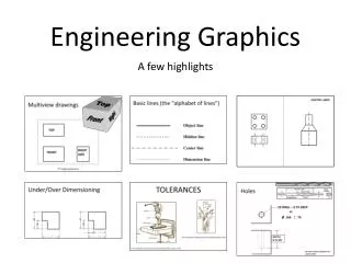
ENGINEERING GRAPHICS1E9 Lecture 2: Orthographic Projections
Projections (1) • Projections transform points from n (here, n = 3) dimensional space into a space of dimension less than n (here, n = 2) • Points to be considered, • Location of object • Location of observer • Plane of projection • Projectors/lines of projection
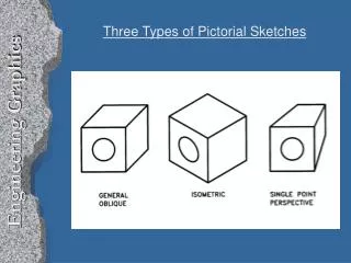
Oblique Projections • Projectors are parallel to each other but not perpendicular to projection plane • An oblique projection shows front and top surfaces that include the three dimensions of height, width, and depth. • The front or principal surface of an object (the surface toward the plane of projection) is parallel to the plane of projection. • Effective in pictorially representing objects
Orthographic Projections • Orthographic projections are drawings where the projectors, the observer or station point remain parallel to each other and perpendicular to the plane of projection. • Orthographic projections are further subdivided into axonometric projections and multi-view projections. • Effective in technical representation of objects
Axonometric • The observer is at infinity & the projectors are parallel to each other and perpendicular to the plane of projection. # • A key feature of axonometric projections is that the object is inclined toward the plane of projection showing all three surfaces in one view. • The length of the lines, sizes of the angles, and proportions of the object varies according to the amount of angle between the object and the plane of projection.
Axonometric The object is tilted with all three coordinate axes are visible in any one view (PP projection plane)
Orthographic (Orthogonal) The object is at rest and two coordinate axes are visible in any one view (PP projection plane)
Multiview Projections • Front surfaces of object is parallel to plane of projection • Projectors or line of sights are perpendicular to projection plane • Projectors are parallel to each other and originate from any point on object
Angles • First angle projection – European System • Third angle projection – American System
First Angle Projection 1 How to draw plan and elevation?
First Angle Projection 2 How to draw end view?
First Angle Projection 3 Points to remember: • The ‘front view’ (or elevation) is the view with maximum information. • The ‘plan’ is below the ‘elevation’ (in projection). • The ‘end view’ is placed on the right if viewed from left side of object and on the left if viewed from right side. • ‘End view’ and plan face inwards from ‘elevation’.
Third Angle Projection 1 How to draw plan and elevation? In 3rd angle projection planes are transparent and objects are viewed through them
Third Angle Projection 2 How to draw end view?
Third Angle Projection 3 Points to remember: • The ‘front view’ (or elevation) is the view with maximum information. • The ‘plan’ is above the ‘elevation’ (in projection). • The ‘end view’ is placed on the right if viewed from right side of object and on the left if viewed from left side. • ‘End view’ and plan face outwards from ‘elevation’.