Download
1 / 54
540 likes | 639 Views
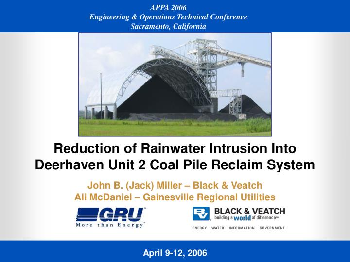
Reduction of Rainwater Intrusion Into Deerhaven Unit 2 Coal Pile Reclaim System. John B. (Jack) Miller – Black & Veatch Ali McDaniel – Gainesville Regional Utilities. Overview.

E N D
Reduction of Rainwater Intrusion Into Deerhaven Unit 2 Coal Pile Reclaim System John B. (Jack) Miller – Black & VeatchAli McDaniel – Gainesville Regional Utilities
Overview Gainesville Regional Utilities (GRU) Recently Installed a Rain Shield Over the Coal Reclaim for Their Deerhaven Unit 2. This Presentation Will: • Describe the Process That Lead to the Decision to Install the Cover • Review the • Design Development • Design Features • Construction Process • Examine the Initial Measurements of Its Effectiveness JBM(8) - 2
About the Authors • Ali McDanielMaterial Science Engineer – GRU’s Project and Construction Manager for This Project • Jack MillerMechanical Engineer – Black & Veatch’s Project Manager for the Feasibility Study and Detailed Design JBM(8) - 3
About GRU • GRU Is a Municipally-Owned Utility Serving the City of Gainesville, Florida for 100 Years • Gainesville Is Located in North Central Florida • GRU Serves 87,000 Retail and Wholesale Customers • Owns and Operates Two Power Plants, John R. Kelly and Deerhaven Generating Stations • Installed Capacity of 611 MW to Serve a Peak Demand of 450 MW JBM(8) - 4
About Deerhaven Unit 2 • Deerhaven Unit 2 Is a 235 MW Pulverized Coal-Fired Steam-Electric Generating Unit • Commissioned in 1982 • Burns Low Sulfur East Kentucky Compliance Coal JBM(8) - 5
Aerial View of Deerhaven Generating Station Looking North Northeast JBM(8) - 6
Problem Definition Annually 58 inches max. 48 inches avg. 34 inches min. • Rain!! • Wet Coal • O&M Impacts Plugging in the Reclaim, Conveying Storage and Milling Systems • Negative Impact to Thermal Efficiency • Can Cause Significant Unit Derates and Relatively Expensive Replacement Power • In 2003, Wet Coal Effects Directly Resulted in the Need for 12,879 MWh of Replacement Energy JBM(8) - 7
Overview of Coal Handling System JBM(8) - 8
Highlights ofCoal Handling Operations JBM(8) - 9
Highlights of Coal Handling Operations • Coal Is Delivered by Unit Trains Carrying About 11,000 Tons • Unloaded From Track Hopper at 3,000 TPH • Conveyed to Dual Discharge Fixed Boom Stacker • Can Build 1,800 Ton Conical Coal Pile on North and South Sides JBM(8) - 10
View of Stockout Tower Looking West JBM(8) - 11
Highlights of Coal Handling Operations • Reclaim System Operates at 500 TPH (2" x 0" Coal at 15% Moisture) • Four Below-Grade Hoppers: Three on the South (Active Reclaim) • One on the North (Emergency Reclaim) • Hoppers Feed a Common 30-Inch Belt Conveyor • Conveys Coal to the Six Storage Bunkers Via a Crusher Tower • Bunkers Hold 18 Hours of Fuel at Typical Burn Rate • Coal Is Fed to Burners Through B&W MPS 75N, DVS Rotating Classifier Pulverizers JBM(8) - 12
Graphic Display – Stockout and Reclaim System JBM(8) - 13
Coal Pile Management Equipment • Excess Coal Is Moved From Stockout Pile to Long-Term Storage Using Dozers and Front-End Loaders • Takes Three Machines Three Days to Move and Spread 11,000 Tons JBM(8) - 14
Analysis and Developmentof Solution JBM(8) - 15
Analysis and Development of Solution • Wet Coal Effects Had Been Manageable Until Coal Fines Content Increased • In Late '90s, Began Using Lower Sulfur East Kentucky Coal • Sizing Changed From Nominal 2" x 0" to ¾" x 0" • Fines Increased Considerably • More Conducive to Plugging When Wet • More Conducive to Excessive Ratholing Above the Reclaim Hopper JBM(8) - 16
Ratholing at the Center Reclaim Hopper Ratholing Provides Direct Path for Rainfall and Runoff to Enter the Reclaim Hopper and Flow Directly Onto Reclaim Belt Primary Source of Entrained Water in the Coal and Attendant Problems JBM(8) - 17
GRU Study • Correlation Between Rainfall and Need for Replacement Energy Due to Unit Derates • Short-Term Rain Events of Greater Than 2 Inches Cause Derates on a Proportional Basis More Rain, More Replacement Energy Needed • Results for 2003 JBM(8) - 18
B&V Study Potential Solutions • Improve Pile Management Practices Reduce Fines Stratification • Modify Reclaim Equipment Water Collecting Gates • Install Alternate Reclaim Above Grade, Dewatering Dozer Trap • Install Cover Over Active Reclaim Intercept Rainfall – GRU’s Preferred Alternative – Estimated Cost $1.5 Million JBM(8) - 19
GRU Economic Analysis • Focused on Cost of Replacement Energy Resulting From Unit Derates • Recognized That 2003 Experience (12,879 MWh) Was Based on Above Average Rainfall • Conservatively Assumed Average Annual Derate of 40 MW for 120 Hours • Correlates to 4,800 MWh of Replacement Energy • Based on Fuel Forecast (Natural Gas and Coal) – Avoidance of Replacement Energy Yielded and IRR of 13.4% Satisfied GRU Threshold JBM(8) - 20
Design JBM(8) - 21
Functional Design Criteria • Sized to Prevent Rainfall From Impinging on Active Reclaim Area • High Enough to Accommodate 1,800 Ton Conical Pile • Maximize Area of Coverage Within Space Between Stockout Tower and Perimeter Drainage Swale • Support System Cannot Impede Movement of Coal by Mobile Pile Management Equipment • Support Structure Should Be Resistant to Contact by Mobile Equipment • Must Accommodate Night Time Pile Management Operations JBM(8) - 22
Other Design Criteria • Design Life: 30 Years • Environment: Subtropical Climate Hot Summers; Mild Winters • Temperature and Humidity: 70 F and 90% – Design 115 F and 100% – Extreme Max 10 F – Extreme Min • Rainfall: 10-Year Return Period, 24-Hour Event 0.30 Inches Per Hour, 7.2 Inches Total • Wind Speed: Per the Florida Building Code (FBC) • Seismic: Aa = .05; Av = .05, Soil Profile S-3 • Grade: 189 msl • Lighting: 5 Footcandles of Illumination, Ability to Control Lighting Level JBM(8) - 23
Design • Foundation System • 16 – 48 Inch x 55 Foot Drilled Piers • Reinforced Concrete Pier Cap Two Piers Per Cap • 2' x 3' Reinforced Concrete Grade Beams • Cover Support Structure • Concrete Columns • Precast Concrete Beams • Top of Support Is 25 Feet Above Grade JBM(8) - 24
Cover Support Structure – Concrete Columns and Beams JBM(8) - 25
Cover and Its Structural Framework • Initial Concept Was a Geodesic Dome • Finally Selected a Rectangular Plan Arrangement to Maximize Coverage Within Allotted Area • Arched North to South Clear Span of 175 Feet • 160 in Length East to West and 91 Feet Above Grade at High Point of Arch JBM(8) - 26
Cover and Its Structural Framework • Trusses: • Fully Triangulated Space Truss • Truss Depth Is 8 Feet • 7 Trusses With 25 Foot Spacing • Fabricated From 8 Inch Wide Flange Aluminum Struts • Lateral Stability Provided by 4 Inch Aluminum Tubing • Framework Is Bolted Together • Skin: 0.050 Inch Thick Aluminum Skin Is Bolted to Frame • Lighting: • Interior: 24 HPS Fixtures Attached to Inside of Cover Framework • Exterior: 8 HPS Fixtures Attached to Support Structure • Each Switch Controls Six Fixtures Provides Adjustability JBM(8) - 27
Construction JBM(8) - 28
Construction • Contracting Approach • Engineering – Black & Veatch (Owner’s Engineer) • Cover Supply (Detailed Design, Furnish and Erect) – Conservatek • General Construction – Yates Construction • Construction Management – GRU • Overall Schedule • Design, Fabrication and Delivery of Cover – 60 days • Erection of Cover – 60 days • General Construction • Original Schedule Was 4 Months • Actual Schedule Was 8 Months JBM(8) - 29
Construction • Site Preparation • For Foundation and Support Structure Construction – Removed 50% of Coal From Active Pile • For Erection of Cover Framework and Skin – Rebuild Minimum Coal Base of 12 Feet to Function as Construction Platform • Coal Base Filled the 175' x 160' Covered Area Plus 30 to 50 Foot Margin on the East West and South Sides • Foundations and Concrete Support Structures • Six Week Delay in Mobilizing Drilled Pier Contractor • Encountered Unforeseen Subsurface Obstructions Causing Damage to Caisson • Installed 16-48 Inch Diameter Drilled Piers • Tied Pairs of Piers Together With Reinforced Concrete Pier Cap • Tied Outboard Pier Caps Together With 2 Foot by 3 Foot Grade Beams JBM(8) - 30
Drilled Pier Caisson JBM(8) - 31
Drilled Pier Installation Equipment JBM(8) - 32
Damaged Drilled Pier Caisson JBM(8) - 33
Pier Cap Form Work • Foundations and Concrete Support Structures • Poured in Place Concrete Columns Were Constructed on the Pier Caps • Precast Support Beams Were Placed on Top of the Columns JBM(8) - 34
Concrete Support Structure – Lifting of Precast Beam JBM(8) - 35
Concrete Support Structure – Positioning of Precast Beam JBM(8) - 36
Concrete Support Structure – Setting of Precast Beam JBM(8) - 37
Completed Concrete Support Structure JBM(8) - 38
Erection of Cover and Supporting Structural Framework • Unique Design of Cover Necessitated Custom Designed Lifting Towers • Framed Two Bays at a Time Lift and Proceed. Once Peak Was Reached, Sheeting to the Mid-Point of the Cover Was Accomplished • The Process Was Conducted Two Bays at a Time in That Manner Until Complete JBM(8) - 39
Erection Towers and Partially Completed Trusses JBM(8) - 40
Positioning Erection Towers – Partially Completed Trusses JBM(8) - 41
North Side of Trusses Resting on Concrete Support – Skin Partially Installed JBM(8) - 42
Skin Installation About 2/3 Complete – Repositioning South Towers JBM(8) - 43
Skin About 2/3 Complete – Opening for Stockout Chute Almost Complete JBM(8) - 44
View of Erection Towers on South Side and Underside of Trusses JBM(8) - 45
Close-Up View of Erection Towers on South Side JBM(8) - 46
South Side of Cover Being Raised Onto Concrete Supports JBM(8) - 47
Completing Setting of Cover on Concrete Supports JBM(8) - 48
Completed Cover Looking Northwest JBM(8) - 49
Completed Cover Looking Northeast JBM(8) - 50