Download
1 / 4
40 likes | 160 Views
Lab-1,Week 1, EML 3016 C- Spring 2003 Electronic Device Cooling.

E N D
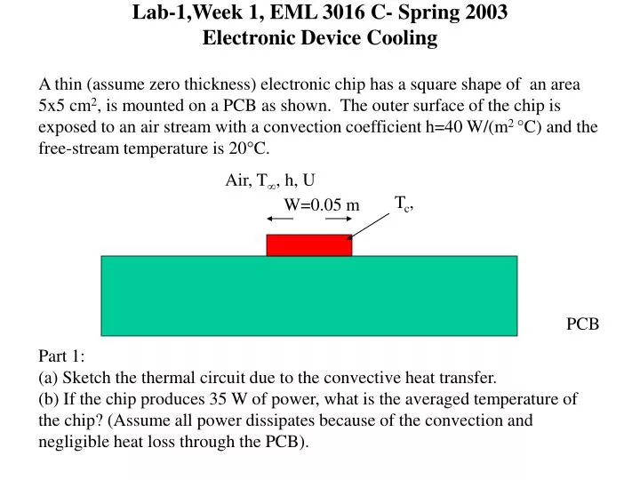
Lab-1,Week 1, EML 3016 C- Spring 2003Electronic Device Cooling A thin (assume zero thickness) electronic chip has a square shape of an area 5x5 cm2, is mounted on a PCB as shown. The outer surface of the chip is exposed to an air stream with a convection coefficient h=40 W/(m2 °C) and the free-stream temperature is 20C. Air, T, h, U Tc, W=0.05 m PCB Part 1: (a) Sketch the thermal circuit due to the convective heat transfer. (b) If the chip produces 35 W of power, what is the averaged temperature of the chip? (Assume all power dissipates because of the convection and negligible heat loss through the PCB).
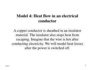
Heat Sink One way to enhance heat transfer from an electronic device is the addition of a heat sink on the top of the device as shown below. In doing so, one can increase the effective area of convective heat transfer. In other words, it decreases the thermal resistance between the electronic chip and the ambient air. PCB In the second part of today’s exercise, we would like to attach a square heat sink consisting of fins with squared cross-section. The dimension of the fin array is given in the next page.
Heat Sink (cont.) L=2.5 cm 11 fins in a row 0.4 cm Material: Aluminum k=237 W/m.K 0.2 cm 0.28 cm W=5 cm Top view of the heat sink
Heat Sink (cont.) Part 2: (a) Draw the thermal resistance circuit for the new configuration with the heat sink attached. (b) Determine the thermal resistance corresponding to the heat sink. (c) If the chip running at a power of 35 W, what will be the operating temperature of the chip with the heat sink. (h=40 W/(m2 °C)) (d) Plot the chip temperature and the thermal resistance of the heat sink as a function of the length of the fins, varying between 0.5 cm to 5 cm (h=40 W/(m2 °C)). Discuss your results. (e) Plot the chip temperature and the thermal resistance of the heat sink as a function of the convection coefficient, varying between 10 to 100 W/(m2 °C). (L=2.5 cm) Discuss your results.