Download
1 / 43
651 likes | 1.28k Views
Chemical Engineering and Materials Science Syracuse University. Valves, Instrumentation, and Control. Process Design CEN 574 Spring 2004. Outline. Types of valves Components of valves Instrumentation: on-line meters Process control review.

E N D
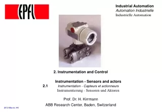
Chemical Engineering and Materials Science Syracuse University Valves, Instrumentation, and Control Process Design CEN 574 Spring 2004
Outline • Types of valves • Components of valves • Instrumentation: on-line meters • Process control review
Valves, Instrumentation, and Control Learning Objectives At the end of this section, you should be able to… • Describe the major types of valves, their operation and characteristics, and draw their standard symbols on a P&ID. • Select an appropriate valve for a specific application. • Identify the function of the major components of a valve. • Select trim and K
List the four most commonly measured variables and draw the symbols for those meters on a P& ID. • Describe the principals of measurement. • Define the variables involved in an PID loop and draw appropriately on a P&ID. • Define tuning. • List the common process problems that lead to unstable PID loops.
References • Chapter 15 in Turton et al., Analysis, Synthesis, and Design of Chemical Processes. • Process Engineers: Take Control! Cecil L. Smith. Chemical Engineering Progress. August 2000.
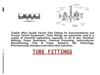
Valve Types • Ball Valve • Butterfly Valve • Gate Valve • Globe Valve • Check Valve
Parts of a Valve 1. Closure member: part of the valve that closes flow (disk, ball, gate, etc.). 2. Actuator: means of operating the valve – hand, gear, chain wheel, motor, solenoid, pressure and flow of the media, air pressure.
3. End fitting: must be specified when buying the valve - butt weld end, compression flange, pipe thread, quick disconnect 4. Material: closure member, housing, seat – stainless steel 5. Packing/seals: seals stem, replaced 6. Seat: where the closure members seals against the valve housing
Ball Valve Sphere with a port in a housing, rotate to expose channel. · Applications: Flow control, pressure control, shutoff, corrosive fluids, liquids, gases, high temp. · Advantages – low pressure drop, low leakage, small, rapid opening · Disadvantages – seat can wear if used for throttling, quick open may cause hammer
Gate Valve Sliding disk, perpendicular to flow Applications: Stop valves, (not throttling), high pressure and temp, not for slurries, viscous fluids Advantages – low pressure drop when fully open, tight seal when closed, free of contamination buildup Disadvantages – vibration when partially open, slow response and large actuating force
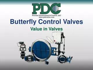
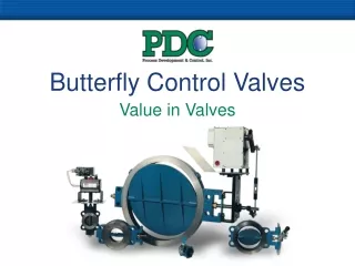
Butterfly Valve rotating disk on a shaft, in a housing Low pressure, large diameter lines where leakage is unimportant Advantages – low pressure drop, small and light weight Disadvantages – high leakage, high actuation forces so limited to low pressures
Check Valves allows flow in only one direction Swing valve similar to butterfly except hinged along one edge rather than rotate about the diameter, used primarily for check valves.
Globe Valve three types (globe, angle and Y), disc or plug moved perpendicular to flow and closes on a ring seat Throttling, general purpose flow control valve Advantages – faster than gate, seat less wear and tear, high pressure drop for pressure control Disadvantage high pressure drop, require considerable power to operate (gears and levers), heavy
Valve Symbols Butterfly Valve Ball Valve Gate Valve Globe Valve
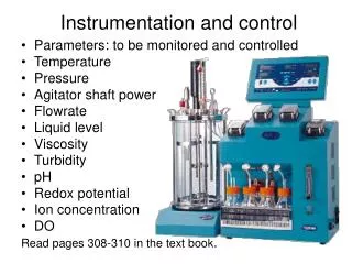
Instrumentation- Form groups of two.- List as many process conditions that can be measured on-line as you can.- List the four most common.
Instrumentation Most commonly measured process conditions: temperature, level, pressure, flow rate, pH. Other variables include composition, moisture, specific gravity, viscosity, dissolved oxygen.
Temperature Thermocouple • Two wires of different metals welded together at the end • When the junction is heated a small electric current proportional to the junction temperature is generated • Types of thermocouple refer to the types of metal – common J,H, K • Thermowell is a sleeve that the thermocouple sits in • Issues – low current, fouling of thermowell Thermister/Resistive thermal detectors (RTD) • Consists of a resister that have a high coefficient of resistance • Resistance = f(temperature)
Flow Rate • Historically the most common method to measure flow rate is the orifice plate. • However, more sophisticated methods are becoming more common because they have less pressure drop.
Calculating pressure drop across and orifice meter • P (psi) = K*(/1726)(velocity2) • K=orifice coefficient usually 0.6-0.8 • =density (lb/ft3) • velocity=velocity through the orifice ft/s • for estimation use orifice ½ of the pipe diameter • Example: assume 4 inch line, 200 gpm, orifice diameter = 2 in, orifice radius = 1 in = 0.083 ft • velocity=(200gal/min)(ft3/7.48gal)(min/60 sec)(1/pi(0.0832ft2)=20.6 f/s • P (psi)=0.7*(62.4)(20.62)/1726=10.7 psi
Level Meters Flow Meters
Process Control: A Review Assignment: Read the Smith article and Turton’s chapter 15 about process control.
Process Upsets T, F, reaction rate, P etc. may change and effect product quality. These variables may change due to equipment failure, intentional production rate changes, cooling water changes, etc. These changes are called process upsets.
Controlled Variables Controlled variables are variables that we want to maintain at constant or specified values (T, P, flow rate, level, etc.).
Manipulated Variables Manipulated variables are variables that we intentionally change to maintain our controlled variable at a constant value. We often manipulate the values by opening or closing a valve.
Measured Variables Measured variables are variables that we measure with a meter (often often the controlled variable or a variable that we use to calculate the controller variable).
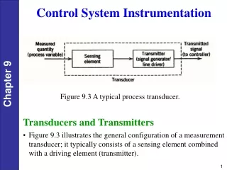
Controller • A unit that reads an INPUT signal and a SET POINT, compares the two, performs a calculation on the difference, and sends out an OUTPUT signal. • Common type of controller: PID = proportional, integral, derivative
Controller meter controller valve INPUT OUTPUT SET POINT (commonly from the operator) (Electrical or pneumatic signal indicated by dashed line.)
Controller Operation • If the INPUT is different than the SET POINT, the OUTPUT signal is changed. • If the INPUT signal is the same as the SET POINT, the OUTPUT signal remains the same.
Types of Control:Feed Back • When the controlled variable changes or is different than the set point, the controller adjusts the manipulated variable to bring the controlled variable back to the set point value. • The controlled variable must change (be different than the set point) for control action to be taken.
Feed Forward • The measured variables are used to change manipulated variables before changes in the controlled variable takes place. Especially useful when there are long lag times in the process. • All factors likely to cause a change in the controlled variable must be taken into account. • Some type of model of process behavior/dynamics must be known, and the accuracy of control is directly linked to the accuracy of control.
Cascade • Uses controllers in series. The first controller’s output is the set point to the second controller. • Reduces lags and allows finer controls, but is more complicated than single loops.
Controlled variables? Control loops? What happens if the light component concentration in the feed decreases?
Distillation Control • Purity of distillate will decrease and amount in overhead will decrease. • Valve CV-1 will open to increase reflux rate in response to concentration change. • Level in reflux drum will drop, so CV-3 will close to reduce overhead flow rate. • Pressure will decrease causing CV-2 to close and cooling water flow rate to decrease. • Level and purity in the bottoms will increase causing CV-5 to open increasing bottoms flow, and CV-4 will close reducing steam
Control Exercise • Form groups of two students • Develop a feedback control loops. • Draw your PFD with control loop on the board.