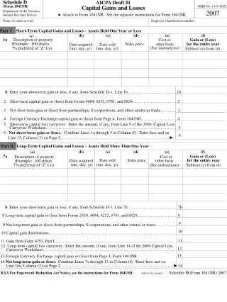
Download
1 / 20
200 likes | 323 Views
Terminal Draft 1. Walter Katz Signal Integrity Software, Inc. IBIS Interconnect July 9, 2014. Overview. Terminal record is restructured a bit to make Post-Layout terminals simple

E N D
TerminalDraft 1 Walter Katz Signal Integrity Software, Inc. IBIS Interconnect July 9, 2014
Overview • Terminal record is restructured a bit to make Post-Layout terminals simple • Pre-Layout terminals associated with a specific Model_name (or a Default package model) use trailing Qualifier names to determine interconnect • Connections • Inverting and Non-Inverting pins on differential models • The explanation will seem overly complex but the examples show how simple it really is, so start off looking at the examples in slides 9:12,14:16 and 18:20 2
Terminal Record • Terminal <#> <location> <ID> {Qualifiers} • <#> • >= 1 • <= Number of Terminals • Unique • Terminals of an interconnect model that do not have a Terminal record are considered unconnected, and the • <location> • Pin|Pin_Sig • Pad|Pad_Sig • Buf|Buf_PCR|Buf_GCR|Buf_PUR|Buf_PDR|Buf_Xref|Buf_Sig • <ID> • <Pin_name>|<Signal_name>|<Model_name>|Default • Qualifiers • Aggressor|Model_name|Default|Inverting|Non-Inverting|Connection(n) 3
Pre-Layout and Post-Layout Rules • A Terminal is Post-Layout if it has no Qualifiers (other than Aggressor) • ID can only be • <Pin_name>|<Signal_name> • A Terminal is Pre-Layout if it has one or more Terminals with Qualifier Model_name or Default • Pre-Layout Terminal Record ID can only be • <Signal_name>|<Model_name>|Default • Additional Pre-Layout Terminal Record optional Qualifiers: • Aggressor • Inverting|Non-Inverting • Connection(n) • An Interconnect Model is Post-Layout if all of its Terminals are Post-Layout • An Interconnect Model is Pre-Layout if any of its Terminal are Pre-Layout 4
Post-Layout <ID> Rules • Pin • Pin_name • Pin_Sig • Signal_name • All pins of Signal_name are shorted to this one node • Pad • Pin_name (or Die_pad_name) • Pad_Sig • Signal_name • All pads of Signal_name are shorted to this one node • Buf|Buf_PCR|Buf_GCR|Buf_PUR|Buf_PDR|Buf_Xref • Pin_name • Buf_Sig • Signal_name • All buffer supply of Signal_name are shorted to this one node 5
Post-Layout {Qualifiers} • Post-Layout Qualifiers are optional and limited to • Aggressor • Limited to Interconnect Models that contain two or more I/O buffers. • If an I/O buffer is an Aggressor, its interconnect does not include all of the crosstalk from its aggressors. • Limited to only Terminal records that have Pin_name records. • Limited to only Pin_names that are buffer I/O pins. • If any buffer I/O Pin_name is Aggressor then that I/O buffer shall be considered a Aggressor. • At least one I/O buffer cannot be an Aggressor. 6
Post-Layout Differential Rules • Differential buffers can be represented as two instances of a single ended buffer, or as “True Differentials” when using [External Models]. • Two single ended buffer instances can have independent supply voltages, or they can share the same supply voltages. When defining supply voltage nodes using Buf_PCR, Buf_GCR, Buf_PUR, Buf_PDR, Buf_Xref keywords the model may choose to have a single node using either the Inverting or Non-Inverting Pin_name, or have two nodes with both the Inverting and Non-Inverting Pin_names. • A True Differential buffer can only have a single set of supply voltage nodes and can use either the Inverting or Non-Inverting Pin_name. 7
Post-Layout Terminal Inferences • All I/O Connections are defined • Buffer instance supply nodes are either • Generated by the IBIS B element • Generated by the EDA tool • Generated from interconnect model using the BUF_PUR, BUF_PDR, BUF_PCR nodes BUF_GCR • Generated from a Buf_Sig node in conjunction with the Pin-Mapping record that associates Signal_name with buffer supply nodes 8
Post-Layout Model Examples • Single DQ (A1) • Terminal Pin A1 • Terminal Buf A1 • Single DQS (D1,D2) (Differential) • Terminal Pin D1 • Terminal Pin D2 • Terminal Buf D1 • Terminal Buf D2 9
Post-Layout Model Examples • Crosstalk (coupled) • One DQ (A2) victim, two DQ (A1 and A3) aggressors • Terminal Pin A1 Aggressor • Terminal Buf A1 Aggressor • Terminal Pin A2 • Terminal Buf A2 • Terminal Pin A3 Aggressor • Terminal Buf A3 Aggressor 10
Post-Layout Model Examples • VDD: All Pins connected to VDD shorted, all buffers connected to VDD shorted • Terminal Pin_Sig VDD • Terminal Buf_Sig VDD • VDD: Pins connected to board “bed spring” model, all buffers connected to VDD shorted • Terminal Pin P1 • Terminal Pin P2 • Terminal Pin P3 • Terminal Pin P4 • Terminal Pin P5 • Terminal Buf_Sig VDD 11
Post-Layout Model Examples • VDD: Pin terminals connected to board “bed spring” model, buffer terminals connected to individual buffer Pullup Reference • Terminal Pin P1 • Terminal Pin P2 • Terminal Pin P3 • Terminal Pin P4 • Terminal Pin P5 • Terminal Buf_PUR A1 • Terminal Buf_PURA2 • Terminal Buf_PURA3 • Terminal Buf_PURA4 12
Pre-Layout Model_name Qualifier • ID is a Model_name or Model_selector name • If [Model] is differential, Inverting or Non-Inverting Qualifier is required • If more than one Connection, then Connection(n) is required • Aggressor is optional • Power supplied to buffer is either • Generated by B-Element • Generated by EDA tool • From Buf_SIG • This can be problematic if different instances of the same model have different Pin-Mapping supply Signal_names 13
Pre-Layout Model Examples • One DQ • Terminal Pin DQ Model_name • Terminal Buf DQ Model_name • One DQS • Terminal Pin DQS Model_name Non-Inverting • Terminal Pin DQS Model_name Inverting • Terminal Buf DQS Model_name Non-Inverting • Terminal Buf DQS Model_name Inverting 14
Pre-Layout Model Examples • Crosstalk (coupled) • One DQ victim, two DQ aggressors • Terminal Pin DQ Model_name Aggressor Connection(1) • Terminal Buf DQ Model_name Aggressor Connection(1) • Terminal Pin DQ Model_name Connection(2) • Terminal Buf DQ Model_name Connection(2) • Terminal Pin DQ Model_name Aggressor Connection(3) • Terminal Buf DQ Model_name Aggressor Connection(3) 15
Hybrid Pre-Layout and Post_Layout Model Example • Crosstalk (coupled) • One DQ victim, two DQ aggressors, one DQS aggressor Terminal Pin DQ Model_name Aggressor Connection(1) Terminal Buf DQ Model_nameAggressor Connection(1) Terminal Pin A2 Terminal BufA2 Terminal Pin DQ Model_nameAggressorConnection(2) Terminal Buf DQ Model_nameAggressor Connection(2) Terminal Pin DQS Model_name Aggressor Connection(3) Non-Inverting Terminal BufDQS Model_name Aggressor Connection(3)Inverting Terminal Pin DQS Model_name Aggressor Connection(3)Non-Inverting Terminal BufDQS Model_name Aggressor Connection(3)Inverting 16
Pre-Layout Default Qualifier • ID is Default also • If differential, Inverting or Non-Inverting Qualifier is required • If more than one Connection, then Connection(n) is required • Aggressor is optional • Power supplied to buffer is either • Generated by B-Element • Generated by EDA tool 17
Pre-Layout Model Examples • One Single Ended • Terminal Pin Default Default • Terminal BufDefault Default • One Differential • Terminal Pin Default Default Non-Inverting • Terminal Pin Default Default Inverting • Terminal Buf Default Default Non-Inverting • Terminal Buf Default Default Inverting 18
Pre-Layout Model Examples • Crosstalk (coupled) • Three Single Ended: one victim, two aggressors Terminal Pin Default Default Aggressor Connection(1) Terminal Buf Default Default Aggressor Connection(1) Terminal Pin Default Default Connection(2) Terminal Buf Default Default Connection(2) Terminal Pin Default Default Aggressor Connection(3) Terminal Buf Default Default Aggressor Connection(3) 19
Hybrid Pre-Layout and Post_Layout Model Example • Crosstalk (coupled) • One DQ victim, two single ended aggressors, one differential aggressor Terminal Pin Default DefaultAggressor Connection(1) Terminal Buf Default DefaultAggressor Connection(1) Terminal Pin A2 Terminal BufA2 Terminal Pin Default DefaultAggressor Connection(2) Terminal Buf Default DefaultAggressor Connection(2) Terminal Pin Default DefaultAggressor Connection(3) Non-Inverting Terminal Buf Default DefaultAggressor Connection(3)Inverting Terminal Pin Default DefaultAggressor Connection(3)Non-Inverting Terminal Buf Default DefaultAggressor Connection(3) Inverting 20