Download
1 / 31
310 likes | 436 Views
Why Do We Need a PS X-Rays Source? Deflecting Cavities for Light Sources. Ali Nassiri Advanced Photon Source LHC-CC08 Mini-Workshop Brookhaven National Laboratory February 25-26, 2008. Acknowledgements.

E N D
Why Do We Need a PS X-Rays Source?Deflecting Cavities for Light Sources Ali Nassiri Advanced Photon Source LHC-CC08 Mini-Workshop Brookhaven National Laboratory February 25-26, 2008
Acknowledgements B. Adams, A. Arms, N. Arnold, T. Berenc, M. Borland, T. B. Brajuskovic, D. Bromberek, J.Carwardine, Y-C. Chae, L.X. Chen, A. Cours, J.Collins, G. Decker, P. Den Hartog, N. Di Monti, D. Dufresne, L. Emery,M. Givens, A. Grelick, K. Harkay, D. Horan, Y. Jaski, E. Landahl, F. Lenkszus, R. Lill, L. Morrison, A. Nassiri, E. Norum, D. Reis, V. Sajaev, G. Srajer, T. Smith, X. Sun, D. Tiede, D. Walko, G. Waldschmidt, J. Wang, B. Yang, L. Young V. Dolgashev (SLAC) R. Rimmer, H. Wang , P. Kneisel, L. Turlington (JLab) Derun Li, A. Zholents (LBL) K. Hosoyama (KEK) L. Bellatoni (FNAL) J. Shi (Tsinghua University- Beijing). PhD student
Outline • Science case • Rf crabbing concept • X-ray performance • Beam dynamics issues • Technology options and challenges • Summary
A New Era of Ultrafast X-ray Sources ERL kHz–GHz LCLS: 120Hz SPPS 10Hz ps upgrade 120–1kHz,?) Slide courtesy: D. Reis, UM
Atomic Ex. States Proton Transfer Period of Moon Bound Water Relaxation Ex. State Fe57 Cell Division Rotations Bond Breakage DNA Unfolding Protein Folding Phonon Frequency Lasers ps source X-ray Techniques 106 104 102 100 10-2 10-4 10-6 10-8 10-10 10-12 10-14 10-16 Ultrasonic EPR NMR Storage Ring Sources X-ray FELs Slide courtesy D. Reis, U. Michigan
Science Enabled by ps Sources • The field of time domain scientific experiments using hard x-rays from synchrotron radiation sources is gaining momentum. • The time range covered by ongoing and future experiments is from sub-picoseconds to thousands of seconds which is 16 to 17 decades of spread. • The scientific disciplines which will benefit from these studies include: • Atomic and molecular physics • Biology and chemical science • Photochemistry in solution • Condensed matter physics • Ultrafast solid state phase transition • Engineering and environmental science • Material and nuclear science
Existing and Future Sources • Table-top plasma sources • Short pulse 300 fs - 10 ps • Divergent radiation - low flux • Low rep-rate (10- 1kHz) • Not tunable (target dependent) • Storage Rings • ~100-ps duration pulse • Spontaneous x-ray radiation • High average brightness at high repetition rate • Laser Slicing ( ALS, SLS, BESSY) • Short pulse 100 -300 fs • Rep-rate kHz • Low flux 105 ph/s @ 0.1%bw • Not effective at high-energy sources • Linacs ( LCLS/XFEL) • Short pulse 100 fs • Fully coherent • Extremely high brilliance • Low rep-rate (100 Hz) • Limited tunability
What do the Users Want? • Peak brightness isn’t everything • What is important is a combination of: • Short pulse ( 1ps or below) • Tunability • Repetition rate ( 1 kHz to CW) • Accessibility • Average number of photons • Focusibility Flexible source will enable new physics
s* CF3Br preferred polarization E • Coherent diffraction imaging of molecules at higher field strength • Monitor laser-induced distortion with sub-Angstrom resolution • Current 1012 W/cm2 @ 100 ps to 1014 W/cm2 @1ps • Test ab initio understanding of dynamics polarizability • Non-perturbative multiphoton effects • Coherent diffraction imaging of molecules in a field-free environment • Dynamics of laser-controlled motions: rotational and vibrational (phonon) • Photoionization dynamics from aligned molecules Dipole interaction between molecules and laser electric field short x-ray pulse (ps) is essential to match the alignment time scale e- Bromotrifluoromethane Orbital alignment in ultrafast field ionization 1014-1015 W/cm2 Slide courtesy: L. Young, AMO Group, ANL X-ray absorption by laser-aligned molecules ~1012 W/cm2
Time-resolved Bragg Diffraction: (laser pump/x-ray probe) • Coherent Acoustic Phonons • Impulsive strain propagation in Indium Antimony • Quantitative measurements of atomic displacements • Track energy flow from optical excitation into lattice modes Time-resolved x-ray diffraction proportional mode Experiment: InSb 111, 10mJ/cm2 Simulation: 100ps & 1.25mdeg conv. Reis et al. Phys Rev. Lett.(86) 2001
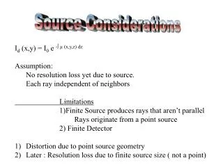
X-rays Slitting y Concept • Use transverse-deflecting rf cavities to impose a correlation (“chirp” between the longitudinal position of a particle within the bunch and the vertical momentum. • The second cavity is placed at a vertical betatron phase advance of n downstream of the first cavity, so as to cancel the chirp. • With an undulator or bending magnet placed between the cavities, the emitted photons will have a strong correlation among time and vertical slope. • This can be used for either pulse slicing or pulse compression. X-ray pulse compression A. Zholents, P. Heimann, M. Zolotorev, J. Byrd, NIM A 425(1999), 385
Rf Curvature and Frequency Choice Can get the same compression as long as h*V is constant. Higher h and lower V: smaller maximum deflection and less lifetime impact. Higher V and lower h: more linear chirp and less need for slits. Higher h and maximum V: shortest pulse, acceptable lifetime
X-ray performance 26.5 m is the distance to a 2mm 3mm aperture in the ID7 beamline. Aperture is typically set 0.5 mm in both planes. (E. Dufrense) Data courtesy R. Dejus Plots courtesy M. Borland
Beam dynamics issues – emittance growth1 • In an ideal machine • TOF dispersion between cavities due to beam energy spread • Uncorrected chromaticity • Coupling of vertical motion into horizontal plane by sextupoles • Quantum randomization of particle energy over many turns • Additional source of growth – real machine • Errors in magnet strengths between the cavities • Roll of magnets about beam axis • Orbit error in sextupoles • Errors in rf phase and voltage • Side effects • It limits brightness • It limits how short an x-ray pulse can be acheived 1 M. Borland, Phys. Rev. ST Accel Beams 8, (2005)
Emittance growth vs. deflecting voltage Plots courtesy M. Borland
Summary of Tolerances • Differential errors are assumed to be “static” • CM errors may be dynamic, but conservatively evaluated as static • Temperature control should be AGARA. We’ll have to manage temperature-related drifts with phase shifters and attenuators. • Tolerance on timing signal from crab cavity to users: ±0.9 deg Slides courtesy M. Borland
Beam stability Analysis - HOM/LOM • For three-cell cavities with coupler at end cell using 3D model for R, Q, and R/Q values • Qs of longitudinal and horizontal planes are very low ( 20 – 200) • Worst vertical plane HOM has a Q of 4100 • Horizontal and vertical planes are stable with synchrotron radiation • No need for coherent damping L. Emery
Cavity Design Evolution June 05* Nov 07** * V. Dolgashev, SLAC * * V. Dolgashev, SLAC, G. Waldschmidt, A. Nassiri
RF Parameters after Structural Analysis Mechanical Design Physics Parameters Copper Cavity resonances Stability limit Cooling channels Vacuum Frequency sensitivity maxima Cavity Design Flow • Iterative process evaluated rf / physics / mechanical design and structural analysis • Parallel analysis optimized the cavity performance • Final analysis performed on the overall effect of structural analysis due to thermal effects on cavity rf parameters (frequency shift and modified thermal loading).
APS Short Pulse X-Ray Normal-Conducting Cavity Design* Normal-conducting 3-cell cavity with damping waveguide and dual input couplers Input coupler Water header Tuning pins Ridged damping waveguide Rectangular damping waveguide Damping material is attached to each damping waveguide flange *Collaboration with V. Dolgashev (SLAC)
Damper Flange Coupler Coupler Damper Flange Damper Flange Slide courtesy: L. Morrison
Input Coupler Notch Filter Coaxial Coupler Main He vessel Sub He vessel RF Absorber KEK Single-Cell 500 MHz Crab Cavity* 1/3-scale prototyping started in 1994 Crab cavity was successfully operated at KEK in spring ‘07 * K. Hosoyama, KEK
APS 2.8 GHz Superconducting Single-Cell Deflecting Cavity1 Input Coupler / HOM damper Deflecting cavity LOM/ HOM damper HOM dampers Waveguide damper replaces KEK coaxial coupler Compact single-cell cavity / damper assembly 1 In collaboration with JLab and LBL
Deflecting Mode Magnetic field magnitude • Dampers create a 37% increase in peak magnetic field • Strong damping requirements for APS necessitate damper proximity to cavity • Total number of cavities is determined such that peak magnetic field is < 100 mT • 12 mm clearance between cavity and dampers (on either side) for tuning plates. • An elliptical beam pipe was investigated for reducing peak magnetic field, but little improvement was found in the ratio mT/MV. Peak B-field Deflecting mode parameters with and without dampers
Lower Order Mode • Deflecting mode couples weakly to LOM waveguide • LOM waveguide stub was optimized exclusively for LOM damping • LOM splits into two modes as the stub length approached optimal value • Nominal stub length was 95 mm, or ~ LOM Mode Splitting Stub length Lower-order-mode parameters with and without dampers Microwave Studio and GdFidl results from varying stub length
Longitudinal Wakefield Dissipation Volts / pC Distance (m) Deflecting Cavity Broadband Longitudinal Impedance APS Longitudinal Beam Stability APS stability limit: Impedance (MOhm) Broadband impedance for 24 cavities Frequency (GHz)
T2 T2 ID VC P P Deflecting Cavity Layout - Schematic 8000 mm 190 mm 4592.7 mm 190 mm 2920 mm Space available for cryo-modules + bellows 107.3 mm V T1 B B B T1 V 12 cavities + cryomodule Gate valve Bellows Bellows 400 mm Thermal intercept 4100 mm Created:1/16/08 Rev: 00
CW SRF - RF Control Challenges • Differential Phase Error Specification: ±0.04 deg • Differential Voltage Error Spec: ±0.29 % • Architecture Tradeoffs: • Single Drive Amplifier: Correlated errors cancel, but need individual I/Q modulators • Individual Drive Amplifiers: Provides individual low level control, but residual phase noise is uncorrelated. • Self-Excited Loop & Tuner Control Algorithms for fast recovery from quench/trips in presence of large static Lorentz detuning (JLab has made excellent progress in this area) • Microphonics Mitigation • Calibration Algorithms (cancel kick, reduce drift) • Phase stable reference & cable plant • Low noise down-conversion Slide courtesy T. Berenc
Summary • The short X-ray pulse generation at the synchrotron light sources will open up new frontiers in time domain science using X-ray techniques to study structural dynamics included but not limited to: • Condensed Matter, Chemical and Biological, Gas Phase Dynamics • Zholents’ scheme has been considered by the synchrotron facilities ( ALS, Spring8, ESRF, DIAMOND, ANL) and as applied to the Advance Photon Source has been studied extensively • Both normal conducting room-temperature and SRF option are feasible with significant advantages of SRF • Is not limited to SR bunch trains fill patterns • Higher flux and higher repetition rates up to CW • It is complimentary to LCLS with the added advantage of energy tunability which is a unique feature in comparison to XFEL sources • Provides spectral coverage and resolution that is necessary in detecting electronic and nuclear geometry on ps-time scale • Light source-based short x-ray pulse generation via Zholents’ scheme has the capability of accommodating multiple users • ANL-APS is taking a lead to develop an SRF deflecting system generating ps-type x-ray pulses in collaboration with JLab and LBL • We welcome and invite more collaborators to join this effort.