Download
1 / 30
510 likes | 975 Views
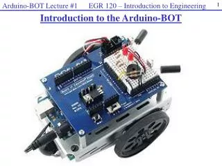
Intro to the Arduino. Topics: The Arduino Digital IO Analog IO Serial Communication. Topic 1 : Meet Arduino Uno. Getting Started. Check out: http://arduino.cc/en/Guide/HomePage Download & install the Arduino environment (IDE) (not needed in lab)

E N D
Intro to the Arduino Topics: The Arduino Digital IO Analog IO Serial Communication
Getting Started • Check out: http://arduino.cc/en/Guide/HomePage • Download & install the Arduino environment (IDE) (not needed in lab) • Connect the board to your computer via the USB cable • If needed, install the drivers (not needed in lab) • Launch the Arduino IDE • Select your board • Select your serial port • Open the blink example • Upload the program
Arduino IDE See: http://arduino.cc/en/Guide/Environment for more information
Input/Output Image from Theory and Practice of Tangible User Interfaces at UC Berkley
Topic 2: Digital Input/Output • Digital IO is binary valued—it’s either on or off, 1 or 0 • Internally, all microprocessors are digital, why? 1 0
Arduino Digital I/0 www.mikroe.com/chapters/view/1 • pinMode(pin, mode) • Sets pin to either INPUT or OUTPUT • digitalRead(pin) • Reads HIGH or LOW from a pin • digitalWrite(pin, value) • Writes HIGH or LOW to a pin • Electronic stuff • Output pins can provide 40 mA of current • Writing HIGH to an input pin installs a 20KΩ pullup
IO Pins Image from Theory and Practice of Tangible User Interfaces at UC Berkley
In-class Exercise 1: Digital IO • Use a push-button to turn ON/Off LED
Topic 3: Analog Input • Think about music stored on a CD---an analog signal captured on digital media • Sample rate • Word length
Arduino Analog Input • Resolution: the number of different voltage levels (i.e., states) used to discretize an input signal • Resolution values range from 256 states (8 bits) to 4,294,967,296 states (32 bits) • The Arduino uses 1024 states (10 bits) • Smallest measurable voltage change is 5V/1024 or 4.8 mV • Maximum sample rate is 10,000 times a second Image credit: Tod Kurt
How does ADC work? • How does ADC work • Excel Demonstration
Topic 3: Analog Output • Can a digital devise produce analog output? Image from Theory and Practice of Tangible User Interfaces at UC Berkley • Analog output can be simulated using pulse width modulation (PWM)
Pulse Width Modulation • Can’t use digital pins to directly supply say 2.5V, but can pulse the output on and off really fast to produce the same effect • The on-off pulsing happens so quickly, the connected output device “sees” the result as a reduction in the voltage Image from Theory and Practice of Tangible User Interfaces at UC Berkley
PWM Duty Cycle output voltage = (on_time / cycle_time) * 5V Image credit: Tod Kurt Fixed cycle length; constant number of cycles/sec
PMW Pins • Command: analogWrite(pin,value) • value is duty cycle: between 0 and 255 • Examples: • analogWrite(9, 128) • for a 50% duty cycle • analogWrite(11, 64) • for a 25% duty cycle Image from Theory and Practice of Tangible User Interfaces at UC Berkley
In-class Exercise 2: Analog IO Part 1: A light theremin
In-class Exercise 2: Analog IO Part 2: Add an LED • Add a 330 ohm resistor and an LED to pin 9 • Using the analogWrite() command, set the intensity of the LED as a function of the value of prReading
Topic 4: Serial Communication Image from http://www.ladyada.net/learn/arduino/lesson4.html
Serial Communication • Compiling turns your program into binary data (ones and zeros) • Uploading sends the bits through USB cable to the Arduino • The two LEDs near the USB connector blink when data is transmitted • RX blinks when the Arduino is receiving data • TX blinks when the Arduino is transmitting data todbot.com/blog/bionicarduino
Some Commands • Serial.begin() • - e.g., Serial.begin(9600) • Serial.print() or Serial.println() • - e.g., Serial.print(value) • Serial.read() • Serial.available() • Serial.write() • Serial.parseInt() • Example Program
Serial-to-USB chip---what does it do? The LilyPad and Fio Arduino require an external USB to TTY connector, such as an FTDI “cable”. In the Arduino Leonardo a single microcontroller runs the Arduino programs and handles the USB connection. Image from Theory and Practice of Tangible User Interfaces at UC Berkley
Two different communication protocols Serial (TTL): Image from http://www.fiz-ix.com/2013/02/introduction-to-arduino-serial-communication/
USB Protocol • Much more complicated Image from http://en.wikipedia.org/wiki/USB
In-class Exercise 3: Serial Communication Modify your program from in-class exercise 2-part 2 to control the intensity of the LED attached to pin 9 based on keyboard input. Use the Serial.parseInt() method to read numeric keyboard input as an integer. An input of 9 should produce full intensity and an input of 0 should turn the LED off.