Download
1 / 67
680 likes | 898 Views
The Fundamental Component. Electronics Club and IBot Club. What is a Breadboard?. Literally, a breadboard is a plank of wood intended for cutting bread on. Electronics Club and IBot Club. Here is the Answer.

E N D
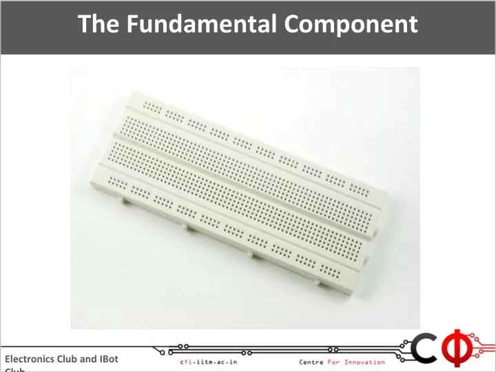
The Fundamental Component Electronics Club and IBot Club
What is a Breadboard? Literally, a breadboard is a plank of wood intended for cutting bread on. Electronics Club and IBot Club
Here is the Answer Breadboard is a platform for quick prototyping of electrical circuits without using the soldering iron. I will tell you about it in the next section of the workshop. Electronics Club and IBot Club
Backside of a Breadboard Electronics Club and IBot Club
Connections On a Breadboard The horizontal holes on each side of the breadboard are connected together. Anything plugged into these holes will be connected together. The horizontal holes on one side are not connected to those on the other. Electronics Club and IBot Club
Connections On a Breadboard The first five and the last five vertical strips are electrically connected. The outer strip is usually used as 5V and the inner ones as GND. Usually the first five and the last five strips are joined by wire. Electronics Club and IBot Club
Making Connections on a Breadboard • 5V connections are in Red. • GND connections are in Black. • Other connections are in any other colour. • Single strand wires are used for connections. • Connections must be tight. • No wire without insulation must be seen on the bread board. Electronics Club and IBot Club
Right vs Wrong Electronics Club and IBot Club
Two Domains Electronics Club and IBot Club
Integrated Circuits • These components perform a specific function based on the inputs given to the pins. • Each of the ICs have a pinout diagram which gives the relation between the inputs and the outputs. Electronics Club and IBot Club
Converting 12V to 5V • 7805T IC is used for this. • Every IC has a datasheet which tells you how to use it. • This is the pin out given in the datasheet for the 7805T IC. • When one looks at it with bulge on it towards them, the left pin is the input of 12 V, the centre ground and the right pin output of 5V. Electronics Club and IBot Club
Logic Gates Electronics Club and IBot Club
Motor Driver IC Electronics Club and IBot Club
What do the Pins Mean? • All the GNDs must be connected to ground. • Vss is the power supply to the IC. It must be connected to 5V. • Vs is the voltage to be redirected to the outputs. • If an input is supplied with 5V, the corresponding output is Vs. • If an input is supplied with GND, the corresponding output is GND. • If Enable 1 is connected to 5V, outputs 1 & 2 are enabled. Enable 2 corresponds to outputs 3 & 4. Electronics Club and IBot Club
Circuit Boards • GCB tracks are soldered by hand. • The PCBs are designed in EAGLE and manufactured. Electronics Club and IBot Club
Making PCBs at Home • The design of the PCB is created in EAGLE and its mirror image is printed on glossy paper. • The paper is kept upside down on a copper plate and ironed on to transfer the toner onto the copper plate. Electronics Club and IBot Club
Some basic Electronic Components The crystal is used to generate the signal. There are load capacitors on its pins that help in generating the signal. The capacitors present in other places help to stabilize the voltage. Electronics Club and IBot Club
Some basic Electronic Components CAPACITORS 1- Electrolytic 2- Ceramic Difference - ??? Electronics Club and IBot Club
Some basic Electronic Components POTENTIOMETERS Electronics Club and IBot Club
Some basic Electronic Components DIODES Electronics Club and IBot Club
Some basic Electronic Components MOSFETs and Transistors- Electronically triggered switches MOSFETs Transistors Electronics Club and IBot Club
Some basic Electronic Components Timer ICs Add a sense of time to circuits Electronics Club and IBot Club
Some basic Electronic Components Opto Coupler Electronics Club and IBot Club
MULTIMETER Uses: 1- Check voltage across circuit 2- Check current in circuit 3- Check resistance 4- Connectivity- Check if two things are connected Electronics Club and IBot Club
Do Something Useful with Tech !!! Electronics Club and IBot Club
How does the IR Sensor work? Output 12 V IR LED Phototransistor • The IR LED transmits light in the IR region. Phototransistor makes output 5V if light in the IR region falls on it. Else, it gives 0V. • So, if there is a reflecting obstacle (like white chart paper) present in front of the sensor, the IR light is reflected and falls on the phototransistor and the output is 5V. • If there is no obstacle or a non-reflecting obstacle like black tape present in front of the LED, no IR light falls on the phototransistor and the output is 0V. Electronics Club and IBot Club
Another Common Sensor Electronics Club and IBot Club
Yet Another Sensor Electronics Club and IBot Club
Making a Line Follower Electronics Club and IBot Club
Building the Chassis Electronics Club and IBot Club
Picking Clamps Electronics Club and IBot Club
Clamping Motor-Wheel to Chassis Electronics Club and IBot Club
Fixing of a Castor Wheel Electronics Club and IBot Club
Fixing of a Castor Wheel Electronics Club and IBot Club
How does the Bot look like? Electronics Club and IBot Club
Reminds Me of Wall-E Electronics Club and IBot Club
An Interesting Fact About the Chassis Three points of the chassis are always in contact with the ground. They are the castor and the tips of the two wheels. So, the chassis is always stable and not wobbly. This happens because any three points always lie in a plane and in this case this plane is the ground plane. Electronics Club and IBot Club
Locomotion - Match the Following Movement • Front • Back • Left • Right Rotation of Wheels • Left – Front & Right – Stationary • Left – Stationary & Right – Front • Both wheels front • Both wheels back Electronics Club and IBot Club
Making the Circuit Electronics Club and IBot Club
The Stripping Tool In order to make an electrical connection, you need to strip away part of the rubber insulation at the end of the wire. Using a stripping tool, place the end of the wire (about 1/4 inch) into the hole, clamp down on it, then pull the insulation away. Electronics Club and IBot Club
Shorting the Power Lines Electronics Club and IBot Club
Integrating the Power Supply 7805 T 12 V GND Insert the 7805T as shown and make the required connections to the battery. Battery Electronics Club and IBot Club
Checking the Circuit • Set the Multimeter’s knob to measure voltage of under 20 V. • Hold the probes of the Multimeter between the black and the red wires and see whether the meter reads 5V. Electronics Club and IBot Club
Calibrating the Sensors Insert the 12 V connection and bring the bot onto the arena so that one of the sensors is on the black line. Electronics Club and IBot Club
Adjusting the Potentiometer Adjust the potentiometer on the sensor slowly with a screw driver until the LED on it turns red. Electronics Club and IBot Club
Adjusting the Potentiometer Rotate the potentiometer in the opposite direction a bit so that the LED stops glowing. Electronics Club and IBot Club
Integrating the L293D First Sensor’s VCC Second Sensor’s VCC GND GND L293D GND Electronics Club and IBot Club
Connecting the Inputs • On each side, one of the inputs is always grounded. • The other input is connected to the output of the sensor. Electronics Club and IBot Club
Let’s Do It Left Sensor’s O/P L293D Right Sensor’s O/P Electronics Club and IBot Club
Connecting the Motors • The polarities of the motors are in such a way that if the red wire is connected to 12 V and the black wire is connected to GND, the motor runs in clockwise direction and in opposite direction if connected in opposite manner. • The right motor has to rotate in the clockwise direction and the left one in the anticlockwise direction. • So, the right motor’s red wire must be connected to the output corresponding to the right sensor’s output and the left motor’s black wire must be connected to that corresponding to the left sensor’s output. Electronics Club and IBot Club