Download
1 / 28
280 likes | 405 Views
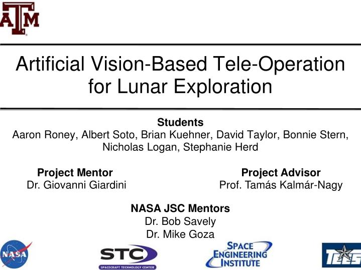
Artificial Vision-Based Tele-Operation for Lunar Exploration. Students Aaron Roney, Albert Soto, Brian Kuehner, David Taylor, Bonnie Stern, Nicholas Logan, Stephanie Herd. Project Mentor Dr. Giovanni Giardini. Project Advisor Prof. Tamás Kalmár-Nagy. NASA JSC Mentors Dr. Bob Savely

E N D
Artificial Vision-Based Tele-Operation for Lunar Exploration Students Aaron Roney, Albert Soto, Brian Kuehner, David Taylor, Bonnie Stern, Nicholas Logan, Stephanie Herd Project Mentor Dr. Giovanni Giardini Project Advisor Prof. Tamás Kalmár-Nagy NASA JSC Mentors Dr. Bob Savely Dr. Mike Goza
Freshman • Freshman • Sophomore • Sophomore • Junior • Senior • Senior • Nicholas Logan • Stephanie Herd • Aaron Roney • Albert Soto • Bonnie Stern • Brian Kuehner • David Taylor • Electrical Engineering • Computer Engineering • Nuclear Engineering • Mechanical Engineering • Mechanical Engineering • Aerospace Engineering • Aerospace Engineering Project Members
Outline • Motivation and Objectives • Ego-Motion Theory • Code Flow • Calibration and Rectification • Hardware • Testing Results • Future Work
Lunar surface exploration • Humanperspective • In safety • With low risk • 3D environment reconstruction • Self location with artificial vision system Motivation
Visual Feedback System for Tele-Operations Objectives • Vision System • Ego-Motion estimation • Environment reconstruction • Tele-Operation System • Remote control mobile unit • Hardware and Mechanical • Implementation
Vehicle Hardware Wireless 802.11 Network Visual System (onboard the Vehicle) Ground Station
Ego-Motion Theory Vehicle Hardware Wireless 802.11 Network Visual System (onboard the Vehicle) Ground Station
Left image Right image 3D Reconstruction Theory urightp uleftp uleftp • It is impossible to compute the 3D coordinates of an object with a single image • Solution: Stereo Cameras • Disparity computation • 3D reconstruction Image vleftp vrightp
Environment Reconstruction • Disparity mapcomputation: • Given 2 images, it is a collection of pixel disparities • Point distances can be calculated from disparities Environment can be reconstructed from disparity map Left Image Right Image Disparity Map
Ego-Motion Estimation • Main goal: Evaluate the motion (translation and rotation) of the vehicle from sequences of images Optical Flow Example • Optical Flow is related to vehicle movement through the Perspective Projection Equation Perspective Projection Equation • Solving will give change in position of the vehicle • Least Square solution
Code Flow Vehicle Hardware Wireless 802.11 Network Visual System (onboard the Vehicle) Ground Station
Image Processing Code Calibration Parameters Logitech QuickCam Deluxe Acquire Images Rectify Images Ego-Motion Estimation Sony VAIO - Pentium 4 Wireless 802.11 Network Ground Station
Mobile Unit Detailed Code Calibration Parameters T = 0.15 sec Acquire Image T = 0.5 sec Rectify Images Apply Distortion Coefficient to Image Matrix Image Parameters: Gray Scale (640x480) … Snapshot Image Matrix Save Image Rectified Image Matrix Wireless 802.11 Network Ground Station Ego-Motion Estimation
Ego-Motion Estimation Overview Discard All non-Identical Points in All images Find Features in Right Image Right Image Track Right Image Features in Left Image Find Features in Left Image Left Image Displacement Vector (X, Y, Z, X-Rot, Y-Rot, Z-Rot) Find Features in New Right Image Track Right Image Features in New Right Image New Right Image New Left Image Image Feature Matrix Find Features in New Left Image Track Right Image Features in New Left Image Calibration Parameters Wireless 802.11 Network T = 3 sec
Calibration and Rectification Vehicle Hardware Wireless 802.11 Network Visual System (onboard the Vehicle) Ground Station
Calibration and Rectification • Calibration: Utilizes Matlab tools to determine image distortion associated with the camera • Rectification: Removes the distortion in the images
Hardware Vehicle Hardware Wireless 802.11 Network Visual System (onboard the Vehicle) Ground Station
Hardware Mobile Unit Base Station Web Cameras TROPOS Router Operator Computer Laptop Wireless 802.11 Command Computer Mobile Unit Linksys Router Wireless 802.11
Improvements Implemented in the System • Improved robustness of the software • Implemented a menu driven system for the operator using Matlab’s network handling protocol • Allowed pictures to be taken • Run Ego-motion • Sending all the results to the operator • Graphic displaying of optical flow • Reduced crashing • Achieved greater mobile unit control
Mobile Unit Vehicle Courtesy of Prof. Dezhen Song FOV1 FOV2 D α Baseline L • Camera support system • 3-DOF mechanical neck: • Panoramic rotation • Tilt rotation • Telescopic capability Horizontal View • Controlled height and baseline length
Testing Result Vehicle Hardware Wireless 802.11 Network Visual System (onboard the Vehicle) Ground Station
Test Environment Light to simulate solar exposure Black background to eliminate background features Walls to eliminate stray light and side shadows Lunar Environment Measured displacements
Test Setup • 25 pictures taken from each location (0, 5, 10 and 15 cm) in the Z direction (perpendicular to camera focal plane), unidirectional movement • Set 1 25 images located at Z=0 • Set 2 25 images located at Z=5 • Set 3 25 images located at Z=10 • Set 4 25 images located at Z=15 • The distances are measured using a tape measure • The cameras are mounted using a semi ridged fixture
Determining the Number of Features Results for 5 cm displacement Used all 100 images Compared each set to the previous • But the accuracy of the results decrease • The standard deviation decreases with the more features 100 Features were selected
Ego-Motion: Example Optical Flow Left Image Optical Flow Right Image
Problems • Images were not rectified • Possible motion of cameras between images • No image filtering • Camera mounting is misaligned • Images acquired from the right camera appear blurry
Conclusions andFuture Work • Demonstrated: • Ego-motion estimation • Environment Reconstruction • Vehicle control and movement • System integration • Future Developments: • Filtering and improving results • Increase the robustness of the vision system • Create a visual 3D environment map
Acknowledgements • Thanks to: • Prof. Tamás Kalmár-Nagy • Dr. Giovanni Giardini • Prof. Dezhen Song • Change Young Kim • Magda Lagoudas • Tarek Elgohary • Pedro Davalos