Download
1 / 16
160 likes | 291 Views
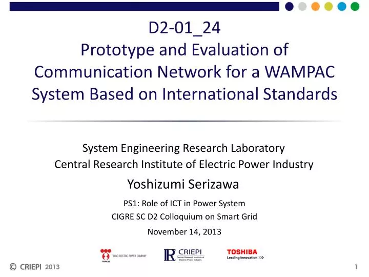
D2-01_24 Prototype and Evaluation of Communication Network for a WAMPAC System Based on International Standards. System Engineering Research Laboratory. Yoshizumi Serizawa. PS1: Role of ICT in Power System CIGRE SC D2 Colloquium on Smart Grid. November 14, 2013.

E N D
D2-01_24Prototype and Evaluation of Communication Network for a WAMPAC System Based on International Standards System Engineering Research Laboratory Yoshizumi Serizawa PS1: Role of ICT in Power System CIGRE SC D2 Colloquium on Smart Grid November 14, 2013 2013
Classification of WAMPAC system Areal range of influence Frequency stability (Wide area) Cascades phenomena Wide Rotor angle stability (Transient stability) Rotor angle stability Voltage stability (Large disturbance) Frequency stability (Islanding) Voltage stability (Small disturbance) Overload Timescale of control Narrow 1 ms 10 ms 100 ms 1 s 10 s 1 min. 10 min. Status data for control Sampled value Rms value Phasor 2013
A configuration of existing WAMPAC system Central Control Computer System-wide state information Dedicated wide area network TE Legend TE G TT G TE Terminal Equipment Transfer Tripping Equipment TT Starter TE Processed result (Generator to be shed) TE TE TT TT G G Shedding command TT TT G G 2013
Int’l standard-based WAMPAC system • CE – WAMPAC-GW communication: • IEC 61970 (CIM) • Wide area communication: • IEEE 802.1 series (Internetworking, provider backbone bridge, etc.) • Related IETF RFCs (Routing, IP multicast, etc.) • Time synchronization: • IEEE 1588 (Precision Time Protocol) • IEEE C37.238 (IEEE 1588 profile for power system) • Cyber security: • IEC/TS 62351-1 to 10 (Data and communication security for power system) • IEC/TR 61850-90-5 (Security profile for synchrophasor communication) CE • Control sequence • Control table • - Setting - Measurement - Status • WAMPAC-GW: • IEEE C37.244 (Phasor Data Concentrator) WAMPAC-GW (CIM – IEC 61850) - Measurement - Status • Control sequence • Control table • PDC - PMU/IED Communication : • IEC61850-90-1 • IEC61850-90-5 • IEEE C37.118.2 (Synchrophasor data transfer) • PMU - IED Communication : • IEC/TR 61850-90-1 (Inter-substation communication) • IEC/TR 61850-90-5 (Synchrophasor communication) - Setting - Control command - Measurement - Status IED PMU IED • PMU: • IEEE C37.118.1 • IEC 60255-118-1 (Synchrophasor measurement) - Control command CB CT, VT CB status and others CE: Central Equipment CIM: Common Information Model WAMPAC-GW: WAMPAC Gateway PMU: Phasor Measurement Unit IED: Intelligent Electronic Device CT, VT, CB status and others 2013
Three types of WAN for WAMPAC system L3/MPLS-based L2-based L2/L3 combined 2013
Restrictions of IEEE 1588 internetworking IED with IEEE 1588 scheme (slave) PTP messages • Sync • Follow_UP • Delay_Req • Delay_Resp etc. Message delivery schemes • Unicast/multicast • Routing etc. L2 switch network with IEEE 1588 scheme IEEE 1588 grand master clock L2 switch network without IEEE 1588 scheme L3 switch or MPLS network without IEEE 1588 scheme IED with IEEE 1588 scheme (slave) IED with IEEE 1588 scheme (slave) 2013
Performance evaluation of IEEE 1588 internetworking Ordinary L3 switch network L3 switch IEEE1588 grand master clock L3 switch L3 switch L2 switch network with IEEE 1588 L2 switch network with IEEE 1588 Connection (b) L2 switch L2 switch L2 switch L2 switch Connection (a) IEEE1588 slave clock IEEE1588 slave clock L2 switch L2 switch L2 switch L2 switch L2 switch L2 switch • Time synchronization errors • Connection (a): Tens of nanoseconds regardless of traffic congestions • Connection (b): 10 and 24μs for background traffic loads of 5 and 95% at the L3 link, respectively, and may be much larger for longer packet traffic IEEE1588 slave clock IEEE1588 slave clock 2013
Performance evaluation of IEEE 1588 with bidirectional IP multicast and MPLS unicast L3 switch(BIDIR-PIM) IEEE1588 grand master clock Rendezvous point L2 switch L3 switch(BIDIR-PIM) L3 switch(BIDIR-PIM) L2 switch IED/PMU (IEEE1588 slave clock) IED/PMU (IEEE1588 slave clock) Link failure L2 switch L3 switch(BIDIR-PIM) L3 switch(BIDIR-PIM) L2 switch IED/PMU (IEEE1588 slave clock) IED/PMU (IEEE1588 slave clock) L3 switch(BIDIR-PIM) • Time synchronization errors • Bidirectional IP multicast: Temporary increase of errors by more than 30 μs (ordinary errors of 1 to 2 μs) upon a sequence of link failure, switchover and recovery • MPLS unicast: Similar to ordinary L2 switch network 2013
Prototype WAMPAC system PMU PMU PMU PMU IED IED IED IED AMP IED/PMU CE RTDS Personal computer WAMPAC-GW IEEE1588 grand master clock Communication cable PDC L3 switch Applications L2 switch L2 switch L3 switch L3 switch Communication units L3 switch L3 switch L2 switch L2 switch 2013
Conclusions 2013 Based on the WAMPAC system architecture, the communication network specifications in terms of function, performance, reliability and cyber security were defined. The time synchronization characteristics were examined for L2/L3 switches with or without IEEE 1588 schemes implemented as well as multicast/unicast operations in IEDs to show a satisfactory synchronization error of a few to tens of microseconds. A prototype WAMPAC system comprising four IEDs was established, and the operating time from fault occurrence to tripping measured less than 50 ms together with satisfactory communication and time synchronization performance.
Special report 2013 Q1-20: What are the cases considered for evaluation of the proposed prototype of Wide Area Monitoring, Protection and Control (WAMPAC) system based on IEEE 1588 international standard? A1-20: While WAMPAC systems may utilize various types of WAN such as L2-based, L3/MPLS-based and L2/L3-combined networks, IEEE 1588 was originally L2-based and immature for wide area L3 networks. Therefore, the evaluations were conducted to examine the internetworking of IEEE 1588 L2 and non-IEEE 1588 L2/MPLS/L3 networks with multicast or unicast scheme in terms of time synchronization errors. The results showed the internetworked system mostly fulfilled the WAMPAC time synchronism requirement, 50 μs.
Cases for evaluation 2013 PTP master-slave time synchronism via PTP-L2 + non-PTP- L3 network with unicast and E2E-TC PTP-L2 network with multicast and E2E-TC/P2P-TC/BC Non-PTP-L3/L2 network with bidirectional IP multicast Non-PTP MPLS network with unicast with respect to traffic congestion with/without priority control, packet losses, network failure/recovery, and master clock switch over (BMC)
Reserve slides 2013
Another configuration of existing WAMPAC system RPU (Remote Processing Unit) CPU (Central Processing Unit) Starter Unit Communication Network Substation • Microprocessor-based • Control computer-based RPU (a) (b) • Pre-calculation • Post-calculation • Disturbance detection RPU Power plant (a) Upstream information: Pre/post-fault status data, starter signal (fault detection) (b) Downstream information (command): Generator shedding, load shedding, system separation 2013
Int’l standard-based WAMPAC system CE Steady-state data flow Data flow in the event ofthe occurrence of a fault • Control sequence • Control scenarios • Setting • Measurement • Status WAMPAC-GW IEC 61850/CIM converter, Phasor Data Concentrator, etc. • Measurement • Status • Control sequence • Control scenarios • Setting • Measurement • Status PMU IED PMU IED • Control command Power system CT, VT, CB CT, VT, CB Generator excitationcontrol system 2013