Download
1 / 31
360 likes | 618 Views
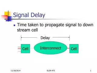
Delay Evaluation. 1. Problem Description 2. Total capacitance model 3. Interconnect delay 4. Distributed RC Model 5. Other complications. 1. Problem Description. Given a pair of pins, compute pin-to-pin delay and possibly output waveform. Delay. Interconnect. Cell. Cell. …. Cell.

E N D
Delay Evaluation • 1. Problem Description • 2. Total capacitance model • 3. Interconnect delay • 4. Distributed RC Model • 5. Other complications ELEN 689
1. Problem Description • Given a pair of pins, compute pin-to-pin delay and possibly output waveform Delay Interconnect Cell Cell … Cell ELEN 689
On-going Research • Difficulty: • Non-linear behavior of device • Complex interconnect parasitic • No well-accepted approach • Any new idea are welcome ELEN 689
Circuit Model • For an inverter … Csink … Csink ELEN 689
Sink Capacitance • Gate capacitance, input capacitance, pin capacitance • Given for standard cells • Can be found using SPICE • Apply an AC voltage and measure current • Average over a range of frequency I ELEN 689
2. Total Capacitance Model • Valid for Rd >> Rmetal • All fanouts have the same delay RC Rd Rd Ctotal ELEN 689
RC Delay 0.35Vdd Vdd Rpd ELEN 689
Driver Resistors • Pull-up and pull-down resistors are not a constant. Which value should we choose? • Use SPICE to compute Rpd and Rpd Ids Vds ELEN 689
RC Delay • Assume constant Rpd, Zhuo Li pointed out in this case Elmore delay is 35% instead of 50% ELEN 689
Linear Delay • Delay is linear in Ctotal • Rd is pull-up/pull-down resistor, assumed to be linear • Interconnect R ignored • Common for >0.5um technology standard cells • Delay = t0+f*Ctotal • t0: Intrinsic gate delay • f: Load factor ELEN 689
Non-Linear: K-factor • Consider input transition time tr/f • Transition time is signal rising/falling time from 20% to 80% • K-factor equation • Delay td=k(tr/f, Ctotal) • Output transition time t’r/f=k’(tr/f, Ctotal) rising time ELEN 689
K-Factor … • Synopsis K-factor form: • Piece-wise-quadratic • For each piece, a*tr+b*Ctotal+c*tr*Ctotal+d • Obtained from SPICE simulation • Ignore interconnect resistance shielding • Widely used ELEN 689
3. Interconnect Delay • Consider the first moment of H(s): ELEN 689
First Moment • Consider h(t) as a probability density function, then m1 is the mean of h(t): • The name moment comes from probability theory ELEN 689
Mean and Median • If impulse response h(t) is symmetric • Then the mean of impulse response equals median of step response, which is 50% delay h(t) hstep(t) t t m1 m2 ELEN 689
Elmore Delay • Since m1 is easy to compute, Elmore used m1 as the delay for the RC circuit • It can be shown for RC trees, h(t) is skewed to the left. Therefore Elmore delay is always an upper bound on the 50% delay ELEN 689
Example 4 1 1 1 1 1 2 3 1 1 1 1 m1_1= –4, m1_2= –7, m1_3= –8, m1_4= –8 ELEN 689
Application of Elmore Delay • Good • Closed form expression, easy to compute • Accuracy is better the ramps • Useful for routing and placement • Bad • Inaccurate • For less than 0.25 um technology • Unbalanced RC trees • Driver ignored • Not useful for timing verification ELEN 689
4. Distributed RC Model • Metal resistance per unit length is increasing, while gate output resistance is decreasing • Portion of delay associated with the interconnect is increasing • Due to resistance shielding, total capacitance is an over estimation ELEN 689
Two Step Approach • Cell delay + interconnect delay • Cell delay and waveform is computed using K-factor • Interconnect delay is computed using Elmore delay or transfer function Interconnect Cell Cell ELEN 689
Sink Waveform • Given linear input waveform, convolution is easy Cell Ctotal ELEN 689
Driving Point Waveform • Ctotal is inaccurate. Use load, driving point waveforms match better RC Rd Rd ELEN 689
K-factor for Load? • Given C1,R,C2 of a load, search a table for linear or piece-wise linear waveform Rd ELEN 689
How to Store Table? • Use load, the k-factor table is 4-dimensional. Too large! Cell ELEN 689
Effective Capacitance Method • Use load • Use 2-dimensional K-factor table Cell Ceff ELEN 689
How to Compute Ceff? • Basic assumption: there exist an input ramp and Ceff, such that the driving point waveforms are the same • Match I and Ie on average Rd Rd I Ie Ceff ELEN 689
Iteration • Assume Ceff=Ctotal • Use f-factor to find transition time trf • Compute current for PI model and Ceff model • If equal then stop, otherwise compute new Ceff and go to 2 ELEN 689
5. Other Complications • Side input • Delay from x to out is different for different values on y • Need characterize for all input combinations Vdd x out y ELEN 689
Simultaneous Switching • Too many cases to consider • Big impact on delay Vdd x out y ELEN 689
Transistor Sizing • Re-sized cells are common • Fast techniques to derive k-factor for re-sized transistors ELEN 689
Readings on Delay Evaluation • J. Rubinstein, P. Penfield Jr., and M. A. Horowitz, “signal delay in RC tree networks,” IEEE Trans. CAD, 1983 • F. Dartu, et al., “A gate delay model for high-speed CMOS circuits,” Proc. ICCAD 1994. • L. C. Chen, et al., “A new gate delay model for simultaneous switching and its applications,”, Proc. DAC, 2001. • E. Acar, et al., “TETA: Transistor-level waveform evaluation for timing analysis,” IEEE Trans. CAD, 2002. ELEN 689