Download
1 / 28
290 likes | 571 Views
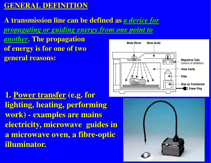
GENERAL DEFINITION A transmission line can be defined as a device for propagating or guiding energy from one point to another . The propagation of energy is for one of two general reasons:.

E N D
GENERAL DEFINITION A transmission line can be defined as a device for propagating or guiding energy from one point to another. The propagation of energy is for one of two general reasons: 1. Power transfer (e.g. for lighting, heating, performing work) - examples are mains electricity, microwave guides in a microwave oven, a fibre-optic illuminator.
We have to treat a conducting system as a transmission line if the wavelength, , of the signal propagating down the line is less than or comparable with the length, l , of the line: l PRACTICAL DEFINITION Associated with transmission lines there may be: • Propagation losses • Distortion • Interference due to reflection at the load • Time delays • Phase changes
The energy propagating down a transmission line propagates as a wave. Different modes of propagation (i.e. different patterns of E and H fields) are possible. These fall into two categories: TE – TRANSVERSE ELECTRIC TM –TRANSVERSE MAGNETIC MODES OF PROPAGATION TEM Modes: In the special case where E and H are both transverse (i.e. at right angles) to the direction of energy flow, the mode is termed TEM. E and H will also be at right angles to each other. TEM – TRANSVERSE ELECTROMAGNETIC TE mode
The details of wave propagation on a transmission line can be deduced from Maxwell's Equations. However, TEM guided waves on a transmission line can also be analysed using a lumped equivalent circuit approach. TEM WAVE EQUATION EQUIVALENT CIRCUIT APPROACH TO TRANSMISSION LINE ANALYSIS Real transmission lines have associated with them: a resistance per unit length, R a capacitance per unit length, C an inductance per unit length, L and a (leakage) conductance per unit length, G. (Note that R represents the resistance of both conductors in the line.)
LDx RDx GDx CDx The existence of an inductance, capacitance, resistance and conductance (per unit length) allows us to represent the transmission line by an equivalent circuit in which each infinitessimal length of transmission line is represented by the same combination of 4 components: EQUIVALENT CIRCUIT FOR A TRANSMISSION LINE Dx To make up the whole line, repeat the equivalent circuit a sufficient number of times.
SYLLABUS Part 1 - Introduction and Basics Lecture Topics 1. General definition Practical definition Types of transmission line: TE, TM, TEM modes TEM wave equation - equivalent circuit approach 2. The "Telegrapher's Equations" Solution for lossless transmission lines: F(t±x/v) Simplest case of F(t±x/v) 3. Direction of travel of cos/sin (ωt ±βx) waves Phase velocity of a wave on a transmission line General transmission line: attenuation
I(x+Dx) = I(x) + DI I(x) LDx RDx V(x+Dx) = V(x) + DV CDx V(x) GDx x+Dx Dx x =
I(x+Dx) = I(x) + DI I(x) LDx RDx V(x+Dx) = V(x) + DV CDx V(x) GDx x+Dx Dx x Similarly, for the voltage V:
Hence: LettingΔx tend to zero: Equations 3 & 4 are called the "Telegrapher's Equations"and are important because they govern the variation of I and V as a function of distance along the line (x) and time (t).
To find how V depends explicitly on time and distance, differentiate Equation 3 with respect to distance, x, and Equation 4 with respect to time, t: Substitute for from 2nd equation into 1st equation:
But we can substitute for I/x from one of the Telegrapher's Equations [Equation (4)]: Rearranging: Using similar steps it can also be shown that: The above two equations govern the voltage and current along a general transmission line.
Note the similarity between these two equations and . . . . . . the wave equations obtained from Maxwell's Equations in Prof. Murray's section: Consider the special case of a lossless transmission line, i.e. one for which R = 0 and G = 0. The previous equations reduce to: Equations 9 and 10 describe voltage and current WAVES travelling down the transmission line.
Any function, F, which has t+x/v or t-x/v as the variable is a solution to these equations, v being a constant with the dimensions of velocity (i.e. units of m/s): Solution to the wave equations for a lossless transmission line. Note that F is a function of x AND t. It is not surprising that F can be any function since we can propagate sine waves, square waves, triangular waves and waves of arbitrary shape down e.g. a coaxial cable.
To verify that F(tx/v) is a solution we need to put F into the wave equation and check that If we do that for F(t-x/v), we find: Therefore F(t-x/v) is a solution of the wave equations for the lossless transmission line (Equations 9 and 10) if 1/v2 = LC (or v = 1/√LC) Similarly you can show that F(t+x/v) is a solution if 1/v2 = LC (or v = 1/√LC)
F(t-x/v) F(t+x/v) The “-” and “+” signs in the variable show which direction the wave is moving in. “-” indicates the wave is moving to the right (+ve x direction) “+” indicates the wave is moving to the left (-ve x direction)
F(t+x/v) Δx Δx t+Δt t x Direction of travel F(t-x/v) P F1 t t+Δt x x1 Consider a fixed point, P, on the moving waveform, i.e. a point with constant F (= F1): F(t-x/v) will be constant if t-x/v is constant If t increases (t→t+Δt), x must also increase if t-x/v is to be constant x increases implies wave is moving to right Similarly for the case of t+x/v – wave is moving to left
Remember from Fourier Analysis that complex signals are made up from components with different frequencies, e.g. : If the velocity of a sine/cosine wave on a transmission line depends on its frequency, different frequency components will move at different velocities, leading to distortion of the signal.
If the velocity, v, depends on frequency the signal will distort as it travels down the line For a lossless line v (= ±1/√LC) will be independent of frequency if L and C are independent of frequency. In this case, any waveform F(t + x/v) will travel along the lossless line without distortion and the line is said to have zero dispersion
Example 2.1 Wave velocity on a transmission line. Derive an expression for the velocity, v, of a wave on a lossless coaxial transmission line in terms of the permeability, m, and permittivity, e, of the medium for : (i) an air-spaced line and (ii) a line filled with a non-magnetic medium. μ = μr μoε = εr εo permeability of free space permittivity of free space (μo = 400π 10-9 Hm-1) (εo = 8.85 10-12 Fm-1) relative permeability of medium relative permittivity permeability of the medium permittivity of the medium
Any function, F(k), can be made up as a sum of sine (or cosine) waves: The simplest solution, F Therefore the simplest function that is a solution to the Wave Equation is just a single sine or cosine function: Say we choose the cosine function and put k=t-x/v:
Recalling that the velocity of a wave, v, is given by v = fl, then f/v = 1/l. Hence: Putting w = 2p f and b = 2p / l (where b is termed the PHASE CONSTANT): V(x,t) = V1cos[wt - bx] b is termed the phase constant because bx gives the phase of the wave at the point x.
Note that we can express the velocity, v, in terms of w and b as well as f andl: Also, note that we can express the cosine function in terms of the complex exponential function: cos(wt - bx) = Re [ej(wt - bx)] = Re [ejwt e-jbx ] sin(wt - bx) = Im [ej(wt - bx)] = Im [ejwt e-jbx ] Hence ej(wt - bx) (= ejwt e-jbx) is also a solution of the wave equation.
Example 2.2 - Effect of a medium on the wavelength of an EM wave (from Kraus, 4th ed.) 3GHz EM radiation is incident on a sheet of polystyrene ( er = 2.7) with a hole. How thick should the sheet be in order that the wave passing through the sheet and the wave through the hole are in phase when they emerge from the sheet? x=0 x=d E↑ E↑
2.3 Properties of a wave on a transmission line. A wave of frequency 4.5 MHz and phase constant 0.123 rad/m propagates down a lossless transmission line of length 500 m and with μr=1. Find: (i) the wavelength (ii) the velocity of the wave (iii) the phase difference between the phasor voltages at the two ends of the line (iv) the time required for a reference point on the wave to travel down the line (v) the relative permittivity of the dielectric in the line
q The TELEGRAPHER'S EQUATIONS: Summary q The equations governing V and I on a general tx line:
q The TELEGRAPHER'S EQUATIONS: Summary q For LOSSLESS LINES (i.e. for R=0 and G=0) V and I satisfy the WAVE EQUATIONS: i.e. voltage and current travel down a transmission line as waves.
q Any function F(t+x/v) is a solution of these wave equations, where v has the dimensions of velocity: q The + & - sign in the variable gives the direction of travel: + indicates wave is travelling to left (i.e. in -x direction) - indicates wave is travelling to right (i.e. in +x direction) q The sine or cosine function is the simplest solution to the wave equations, e.g.: V(x,t) = V1cos[w t-b x] q b = 2p / l is the PHASE CONSTANT (phase difference between two points separated by a distance l is 2p x l / l = b l )