Download
1 / 19
190 likes | 331 Views
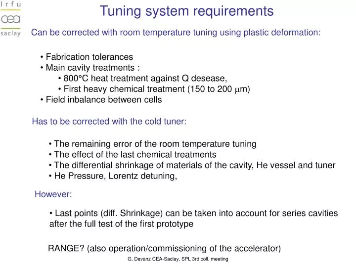
Can be corrected with room temperature tuning using plastic deformation:. Tuning system requirements. Fabrication tolerances Main cavity treatments : 800°C heat treatment against Q desease, First heavy chemical treatment (150 to 200 m m) Field inbalance between cells.

E N D
Can be corrected with room temperature tuning using plastic deformation: Tuning system requirements • Fabrication tolerances • Main cavity treatments : • 800°C heat treatment against Q desease, • First heavy chemical treatment (150 to 200 mm) • Field inbalance between cells Has to be corrected with the cold tuner: • The remaining error of the room temperature tuning • The effect of the last chemical treatments • The differential shrinkage of materials of the cavity, He vessel and tuner • He Pressure, Lorentz detuning, However: • Last points (diff. Shrinkage) can be taken into account for series cavities after the full test of the first prototype RANGE? (also operation/commissioning of the accelerator) G. Devanz CEA-Saclay, SPL 3rd coll. meeting
Slow tuner with symmetric action • Excentric/lever arm provenSaclay design • Planetary gear box (3 stages) • Single NOLIAC 30mm piezo actuator • Stiffness measured on the tuner pneumatic jack = 35 kN/mm • Initially developed for the beta=0.5 5-cell cavity Saclay piezo tuner for 700MHz cavities G. Devanz CEA-Saclay, SPL 3rd coll. meeting
Cavity built in the CARE/HIPPI framework Pulsed tests in vertical cryostat part of the CNI SLHC-PP of FP7 Beta 0.5 704 MHz 5-cell cavity cavity design parameters G. Devanz CEA-Saclay, SPL 3rd coll. meeting
Piezo tuner properties for the Saclay 700 MHz 5-cell cavities • df/dl = 300 kHz/mm • stiffness Kcav = 2.25 kN/mm • stress per mm of tuning = 49 Mpa/mm Differences for the SPL beta=1 cavity • df/dl = 160 kHz/mm • stiffness Kcav = 3.8 kN/mm • stress per mm of tuning 25 Mpa/mm In both cases, the tuning amplitude is limited by the cinematics of the tuner, not by the yield stress of Nb at 2K For the slow tuning and the fast tuning, these properties must be measured in the operating conditions, in our horizontal test cryostat Cryholab • linearity • hysteresis • amplitude G. Devanz CEA-Saclay, SPL 3rd coll. meeting
Piezo tuner stiffness requirements Influence on Lorentz detuning 35 kN/mm Beta=1 5-cell cavity Beta=0.5 5-cell cavity KL = -3.8 Hz/(MV/m)² on beta=0.5 cavity KL = -1 Hz/(MV/m)² on beta=1 cavity For 35 kN/mm : G. Devanz CEA-Saclay, SPL 3rd coll. meeting
Piezo support Role : pre-load the piezo actuator at room temperature with a screw During cooldown, this preload is reduced ( diff. shrinkage of materials) The pre load also changes with cavity positive tuning (piezo is under compression) Having a frame with a stiffness 10 times the cavity stiffness helps maintaining a consistant load state of the piezo Computed stiffness 22 kN/mm, for the beta 0.5 cavity This stiffness should be increased for the SPL cavity G. Devanz CEA-Saclay, SPL 3rd coll. meeting
4.5 K, amplitude = +760kHz corresponding to 2.5 mm -> would be +400 kHz on SPL beta=1 cavity • Mechanical hysteresis measurements will be done at 2 K Beta 0.5 cavity tuning butée mécanique G. Devanz CEA-Saclay, SPL 3rd coll. meeting
Transfer function measurements G. Devanz CEA-Saclay, SPL 3rd coll. meeting
Measurement of ‘bare’ cavity longitudinal mechanical modes Dynamical behavior G. Devanz CEA-Saclay, SPL 3rd coll. meeting
Transfer function measurements ? Phase demodulation measurements at 1.8K in Cryholab TF piezo drive voltage -> cavity detuning can be used to identify the mecanical modes of the system, especially modes generating most detuning (220 Hz) Reproductible measurements except in the 100-160 Hz range (why?) Fcav=703 MHz, far from tuner neutral point G. Devanz CEA-Saclay, SPL 3rd coll. meeting
Piezo detuning (DC) measured at 1.8 K (main tuner parts at 20 K) piezo 44V for 1 mm elongation of the cavity ( ~2 mm for the piezo actuator) Maximum detuning measured at 150V DC = +1 kHz G. Devanz CEA-Saclay, SPL 3rd coll. meeting
Thermal behavior with short braids motor running tuner (b & blk) • Added short braids connected to the He tank: reduced cooling time from 5 to 2.5 days after LHe injection • The motor is not cooled directly in these tests G. Devanz CEA-Saclay, SPL 3rd coll. meeting
Saclay tuner can be fully assembled before installation on a single, closed cavity : Square flange But : Extra requirement for a cavity string assembly in the clean room: A leak test has to be performed in the clean room on the cavity string before it exits the c.r. If the cavity can not withstand the vacuum load (vacuum inside, atm pressure outside), then 3 scenarii possible : Interface/process requirements • The cavity length is held constant during pumping using an easy to clean brace,etc. Then the cavity string is vented, then leaves the clean room, tuner is assembled outside • The cavity length is held constant during pumping using an easy to clean brace,etc. Then the cavity string leaves the clean room under vacuum, tuner is assembled outside, brace removed -> the brace must not interfere with the tuner • The tuner is partly assembled in the clean room before the leak test (time consuming, contamination likely to occur from bearings, heavy parts…) Solution 2 is prefered, the same brace can be used during cavity transport, chem. treatment, … (ttf 9cell cavity technique) This bracing scheme has to be included in the cavity/He vessel/Tuner integration study G. Devanz CEA-Saclay, SPL 3rd coll. meeting
Test in vertical cryostat 1.8 K Beta 0.5 704 MHz 5-cell cavity performance Hpk max = 83 mT • Field emission above 10 MV/m field, high levels of radiation • Wide mulltipactor barrier at 8-10 MV/m also produced lots of radiation • This MP barrier is identified with MUPAC code simulated barrier at 8.1 MV/m, 2 points, at equator • In cryholab, best results equivalent to vert. Cryostat after FE was processed • FE was resumed on 4/5pi mode, even worse! • Cavity was reprocessed with a light BCP, and standard HPWR Test in horizontal cryostat 1.8 K with magnetic shield G. Devanz CEA-Saclay, SPL 3rd coll. meeting
Configuration for pulsed RF in Cryholab G. Devanz CEA-Saclay, SPL 3rd coll. meeting
Feedforward compensation of the klystron P-P/4 phase jump • Coupler conditioning in full reflection at Fdrive=703 MHz, Fcav=702.662 MHz, T=4.5 K • Installation of the CERN 4 channels I/Q measurement crate • No field emission • Cavity reached Eacc max = 16 MV/m at 1.8K, no quench observed yet, FE not observed yet Pulsed RF G. Devanz CEA-Saclay, SPL 3rd coll. meeting
Uncompensated Lorentz detuning during pulse • Klystron phase jump compensated during 4P/P transition to simulate flat top • Slope on the forward voltage due to limited directivity of the WG directional couplers • 25 pulses acquisition to check reproducibility cavity pickup Pulsed RF forward reflected G. Devanz CEA-Saclay, SPL 3rd coll. meeting
Piezo pulses with CW RF Piezo induced detuning G. Devanz CEA-Saclay, SPL 3rd coll. meeting
Conclusion • Piezo tuner is working as expected • Caracterization of the cavity is going on • Lorentz Force Detuning compensation not yet tested, will be done with the fixed and modified HPVS, with long pulses 2ms, 50 Hz • Preliminary compensation tests with 2 ms, 5 Hz are foreseen in the upcoming weeks • The CERN crate is working now as an fast IQ acquisition system, will be used as the piezo controler, and ultimately a adaptive feed-forward for LFD compensation could be implemented. G. Devanz CEA-Saclay, SPL 3rd coll. meeting