Download
1 / 40
400 likes | 571 Views
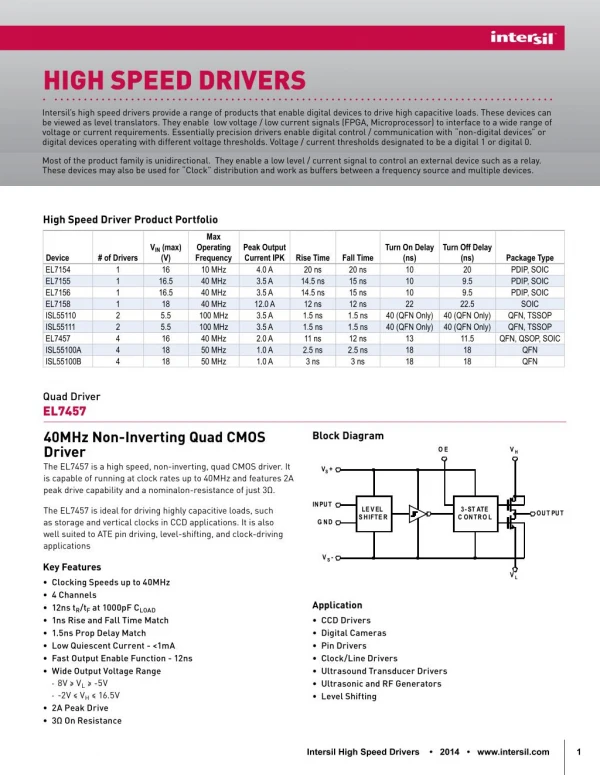
Chapter 9 High Speed Clock Management. Agenda. Inside the DCM Inside the DFS Jitter Inside the V5 PLL. The Digital Clock Manager. Delay Lock Loop Block Diagram. Key ideas: All clocks look the same (more or less) Future clocks resemble current clocks (ie, they are interchangeable).

E N D
Agenda • Inside the DCM • Inside the DFS • Jitter • Inside the V5 PLL
Delay Lock Loop Block Diagram Key ideas: All clocks look the same (more or less) Future clocks resemble current clocks (ie, they are interchangeable)
Compensating for Setup Delays with DLL Basic idea: We can set Td_C = 0
Additional Skew Reduction Place DLL output Centrally, minimize Extra delays
Completing the Picture Clock tree Geometry is Crucial. Delivering clock Uniformly to large Area is the main Idea. Can deliver to Hundreds of LUT Flip flops with Virtually identical “skew”
Configuration & Lock Process General idea: Don’t assert “Locked” To outside world until Done is asserted from The configuration State machine Looks like instantaneous Locking as part powers up
Clock Doubling Capture a period Identify end points Identify middle (50%) Identify 25%, 75% Reassemble pieces
Board Deskewing We seek the ideal Situation with A,B And C all tracking. However, different Environments. Takes two DCMs To lock B to A, and C to A, but can Make outside track Inside the chip
More on Board Deskewing Foreward path delay Note how Locked is used To enable/ Disable the Right hand device Synchronization trick delivers four clocks Worth of reset to the DCM and stops
System Synchronous Applications The Classic, single clocked synchronous system. Looks good, but doesn’t account for clock arriving skewed all over the place to the right hand block(s)
Source Synchronous Applications More common these days. The clock is recreated by the middle box and forwarded to the boxes on the right. This is what DDR SDRAM does, making whichever device is blasting data, also provide the clock for that data to the receivers. You may receive in one case, but transmit in another case, so often both boxes can transmit data and clocks. Depends on which one is Sourcing the Data.
Compare System and Source Synchronous Timing Most Source Synchronous devices have DLL units inside. Data centering can select appropriate setup time by phase Shifting the clock.
Duty Cycle Correction DLLs have ability to correct duty cycle to 50%. This means data clocking with the rising edge has same setup window as data clocking with the falling edge.
Digital Frequency Synthesizer Capabilities Its nice to distribute slow, external clocks and be able to increase speed within the device. Frequency synthesis allows this.
Basic Internal DFS Structure Output Control manages Up/down signal Task: adjust variable ring oscillator so: CLKFX = CLKIN M D
Fixed Value Phase Shift See XAPP 462: ISE software lets you place a phase shift constant Into the programmable phase shifter, to assign clock edges
Dynamic Fine Phase Shift Control Can also do it dynamically, on the fly. Status feedback gives indicator of where you Are in the phase shifting
Clock Jitter Jitter comes from many sources: clock crystal drift noise VCC ripple SSO ground bounce temperature drift, gain change
Peak to Peak Period Jitter Distribution Period jitter captured with digital sampling scope (typically)
Period Jitter Spec. as % Unit Interval Another point of view: consider the amount of time allocated for a data Bit on a line. Call it a Unit Interval. Identify the amount of peak to peak Jitter as a percentage of that Unit Interval. Jitter is a “performance thief”, you must assume it subtracts out of your setup time (usually). Leaves less time available to handle data properly
Peak to Peak Jitter Calculation Adding more devices is done by squaring the device jitter and adding under the radical. Deviation gets divided by “n” as number increases
Virtex 5 Clock Management Tile V5 Clock tile doesn’t Have PMCDs, it Has PLLs, instead.
V5 PLL –High Level PFD = Phase & Frequency Detector CP = Charge Pump LF = Low Frequency Filter VCO = Voltage Controlled Oscillator D = Divisor counter M = Multiplier counter
PLL/DCM Cascades (preferred)
Conclusions • Clocking resources simplify design • DCMs cover standard user domains working with the global clock networks • DFS adds in extra clock multiplication • Phase shifting allows “tweaking” clocks to better center to data • PMCDs are quick/cheap ways to make more clocks and track together • Jitter can be identified, managed and predicted • PLLs can extend the frequency range and reduce overall jitter • Virtex 6 and Spartan 6 resemble Virtex 5 DCMs