Download
1 / 11
110 likes | 199 Views
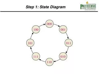
DOES MICE NEED STEP III ?. Somewhat hard to understand MICE Schedule… If the gods are (un)kind it’s possible that SS1, SS2 & FC1 are available at about the same time May be savings in effort & time by skipping STEP III & going straight to STEP IV What are the differences? What would be lost?

E N D
DOES MICE NEED STEP III ? • Somewhat hard to understand MICE Schedule… • If the gods are (un)kind it’s possible that SS1, SS2 & FC1 are available at about the same time • May be savings in effort & time by skipping STEP III & going straight to STEP IV • What are the differences? • What would be lost? • STEP III.1 seemed desirable 1 – 2 years ago when funding for FC modules looked uncertain & schedule was different • Object is to stimulate (provoke) discussion CM25
STEPS III & III.1 • Advertised purpose of Step III is ‘Control of systematics’ • What does that mean? • Presumably compare both spectrometers with same muons • Presumably at central plane • Requires tracking through magnetic field • Propagation of errors on (x…, px…) • This checks Trackers (and software) and alignment • But Step III alignment is not same as Step IV, V, VI alignment • Spectrometer 2 will move each step • Error fields due to shield walls will be different • Modest cooling could be demonstrated in STEP III.1 • For solid absorbers CM25
GEOMETRY OF STEP III / III.1 STEP III.1 has solid absorber – LiH, PE…. 800 + a few mm between M2 Match coils CM25
FOCUS COIL MODULE GEOMETRY OF STEP IV 1520mm • STEP IV ~ 700mm longer than STEP III • Extrapolate tracks 350 mm further on each side • Would this matter for comparison? • Question for Tracker people (?) • LH2 Absorber – but maybe not initially • Can use solid absorbers CM25
OPTICS OF STEP III • Cooling could be measured in STEP III.1 • Optics not very favourable • High (~72cm) beta at absorber • Limited by 300A PSUs of Match Coils • Non-standard (i.e. not design) currents in Match Coils • Next slide…. • 50cm diameter LiH absorber in production CM25
MICE NOTE 158 STEP III MATCH COIL CURRENTS MICE NOTE 199 167 A/mm^2 = 300 A = Current limit Not much overhead Perhaps some erosion of temperature margin ? CM25
STEP IV OPTICS Beta (m) Beta (m) STEP VI STEP IV • STEP IV is STEP VI without two AFCs & RFCCs • Same optics spectometer absorber as steps V & VI • Beta = 42 cm at absorber (baseline 200MeV/c, flip mode) • Better cooling than III.1 • But still quite modest • Match Coils operate at design currents CM25
Flip Mode Non Flip Mode EMITTANCE GROWTH – STEP III Heating % (M. Apollonio CM14) Input Emittance (cm) • Emittance grows – depending on beam emittance • e.g. 10mm beam grows by ~2.5% with no absorber • Any result requires subtraction > raw effect • Not very desirable CM25
Flip Mode Non Flip Mode (M. Apollonio CM14) Input Emittance (cm) EMITTANCE GROWTH STEPS III & VI Heating % Red points = STEP VI From MICE note 0244 • Emittance also grows in empty STEP VI • 10mm beam grows by ~2.7% with no absorber • Presumably the same in STEPS IV and V • STEP IV never studied in detail • In any case, Amplitude Analysis (probably) fixes emittance growth problem for both STEPS III.1 and IV CM25
SUMMARY CM25
THE END CM25