Download
1 / 16
160 likes | 307 Views
U pdated ELQA test procedure. Co-authors: Nuria Catalan Lasheras Mateusz Bednarek Giorgio D’Angelo Richard Mompo. In brief: Why do we need to update this procedure?. We introduce d a new test (MIC) that involves a HVQ of the quench heaters .

E N D
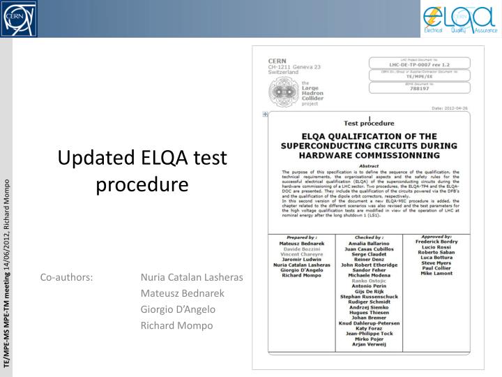
Updated ELQA test procedure Co-authors: Nuria Catalan Lasheras Mateusz Bednarek Giorgio D’Angelo Richard Mompo
In brief: Why do we need to update this procedure? • We introduced a new test (MIC) that involves a HVQ of the quench heaters. • We believe that we need to review the test parameters used in 2009. • We revised the different scenarios. • Written down the rules that apply during Xmas breaks, shutdowns, partial warm-up of a sector based on past experiences. • But the most important... • The voltage parameters for HVQ test derived from EDMS 90327from 2004 (LHC-PM-ES-0001 rev. 2.0) are not taking into account the physical configuration of the machine (presence of EE switches opening simultaneously, vicinity of different circuits) and as a consequence the test voltages should be increasedsignificantly! • c.fNuria’s presentation during MPE-TM meeting of 11 Oct. 2010 • C.f H. Ten Kate presentation to Splice Task Force (Oct. 2010): Test voltage too low to guarantee insulation: Pointed out for the MCS then extended to other circuits • The plan is to use those new test parameters for the ELQA campaign taking place at the end of this run to find all limitations... and to have time to take corrective actions during LS1, before the run at 7 TeV.
SamyChemli circulated a revised version of our test procedure. • 40 persons were notified and we got very few comments!!! • Important comment: • Juan Casas-Cubillos estimated the cost for the repair/replacement of broken cards consecutive to ELQA tests at higher voltages to some 1.6 MCHF. • No strong reaction from the magnet group (except H. Prin who found a minor inconsistency between 2 tables)? • No reaction within our group (except Arjan & Reiner)? We want to make sure that everybody understand the risks involved by those modifications!
Proposed HV test voltages (TP4) Table n°6 (p. 23): New proposed test voltages for TP4 and DOC tests • Legend: • VEE= Ultimate Current * EE res • Vquench from EDMS 90327 • VEEq = VEE + Vquench • V2q = Ʃ Vquench for nested magnets • VGPA is a voltage developped during a Global Power Abort = Max. Voltage seen by a circuit = his own voltage + Max. Voltage on the same cryo. line We make the assumption that a quench does not propagate to the busbars!
Proposed HV test voltages (MIC) Proposed HV test voltages Table n°10 (p. 27): New proposed test voltages for MIC tests Reminder: MIC test involves a HVQ test of each QH vs “Coil+GND”. We revised the test voltage values. The calculation is as follows: U = 1.2 x (VDQHDS + Vquench) = 1.2 x (900+ Vquench) QHs actually see 450V but in case of an internal failure of the HDS, they may see 900 V . Major HW modification would be needed to be able to test above 2000 V. It is foreseen to produce specific HDSs for Separator Dipoles with lower voltages
Conclusions • Some components may not wistand those test voltages (ex: cryo. cards). • A stock of spares need to be prepared… • Several circuitshave never been tested to those voltages(but, in some case, in SM18, single magnets were tested at higher voltages). • We want to identify weaknesses before the warm-up. In some cases, we don’t have any spares (ex: Inner Tripplets). • Breakdowns propagating along a circuit may damage other components such as: QPS controllers, TT sensors... • Redesign HVQ crates to reach 2600 V? • Is it planned to modify the extraction resistance of RQD and RQF circuit during LS1? • Do we need to put our American and Japanese colleagues in the approval list? … Some other limitation/implication, that we are not aware of, may exist?
Exceptions: • The proposed voltage is in most cases taken close to 1.2 times Vmax. However, we have made exceptions in some cases: • *The case of the dipole line is special, as the maximum voltage assumed already on [9] is due to a possible fault on a pole of a power converter. No safety margin is taken however in this case. The safety margin is also reduced for the MCO circuit. • **For the MQ circuit, we recommend to test them at the 1.2 times VEEq to qualify the circuit under the worse conditions seen by the coil. The required voltage difference between bus-bars in line M1/M2 will be seen during the test of the spools and correctors done this time at a higher value. This means that partial test only on the MQ lines is not allowed. All HVQ tests have to be done in all the circuits of the same line, namely M1/M2. • For MCDO, the highest constraint comes from energy extraction of the MCD circuit. There are no values of voltage developed during a quench for this magnet but we assume the voltage is very low given the low nominal current. • Values in red are higher than the withstand voltage currently applied.
Test parameters for SSS magnets (500 series) tested in SM18 (1/2)
Test parameters for SSS magnets (500 series) tested in SM18 (2/2)