Download
1 / 45
460 likes | 602 Views
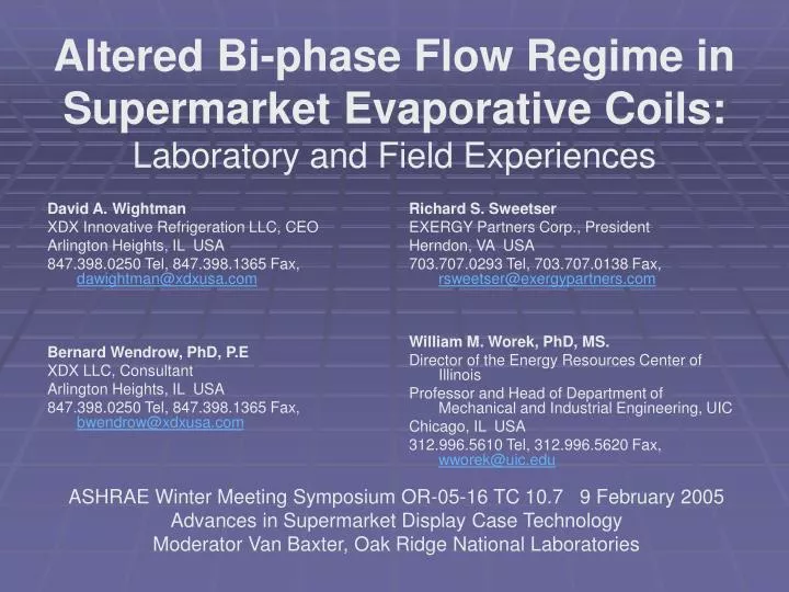
David A. Wightman XDX Innovative Refrigeration LLC, CEO Arlington Heights, IL USA 847.398.0250 Tel, 847.398.1365 Fax, dawightman@xdxusa.com Bernard Wendrow, PhD, P.E XDX LLC, Consultant Arlington Heights, IL USA 847.398.0250 Tel, 847.398.1365 Fax, bwendrow@xdxusa.com.

E N D
David A. Wightman XDX Innovative Refrigeration LLC, CEO Arlington Heights, IL USA 847.398.0250 Tel, 847.398.1365 Fax, dawightman@xdxusa.com Bernard Wendrow, PhD, P.E XDX LLC, Consultant Arlington Heights, IL USA 847.398.0250 Tel, 847.398.1365 Fax, bwendrow@xdxusa.com Richard S. Sweetser EXERGY Partners Corp., President Herndon, VA USA 703.707.0293 Tel, 703.707.0138 Fax, rsweetser@exergypartners.com William M. Worek, PhD, MS. Director of the Energy Resources Center of Illinois Professor and Head of Department of Mechanical and Industrial Engineering, UIC Chicago, IL USA 312.996.5610 Tel, 312.996.5620 Fax, wworek@uic.edu Altered Bi-phase Flow Regime in Supermarket Evaporative Coils:Laboratory and Field Experiences ASHRAE Winter Meeting Symposium OR-05-16 TC 10.7 9 February 2005 Advances in Supermarket Display Case Technology Moderator Van Baxter, Oak Ridge National Laboratories
ABSTRACT • ABSTRACT • Examining Carnot Cycle common assumptions, it is generally believed that the evaporator benefits from a complete stream of liquid entering the coil. The conclusion from this is that maximum enthalpic capacity is achieved by sub-cooling or even super sub-cooling the entering liquid and that anything less than a full column of liquid might limit the amount of heat transfer that the evaporator can accomplish. • The evolution of refrigerant flow testing and mapping is now providing support for a different view. This paper will examine the net effect of an altered bi-phase flow (ABF) regime in evaporative coils, with consideration of a High Vapor Fraction and Turbulent refrigerant flow (HVFT).
Abstract • Two test and verification projects in supermarket medium and low temperature display cases and storage applications provide significant support for examining old rules-of-thumb. • The first involves a deli service case tested under laboratory conditions. This test demonstrates the effect of evaporator operation utilizing an ABF regime and compares this to the operation of a pulse-type electronic expansion valve system. The results demonstrated operation with the ABF regime permitted increased compressor suction pressure, improved product temperature, provided more stable refrigerant temperatures, and improved case product humidity. • The second test and verification project involves field retrofitting of existing direct expansion evaporators to the ABF regime and measuring the results. The resulting change in refrigerant flow regime demonstrated improved performance resulting in consistent and reduced conditioned supply air and product temperatures, improved oil return, reduced compressor discharge temperatures, and increased evaporator pressure. Product Quality and Energy savings were also measurable.
Introduction • Introduction • The industry has had a view that liquid upon entry of the evaporative coil is desirable, and that superheated vapor at the exit of the evaporative coil is necessary. The common view has been that any improvement in Delta-h improves overall system capacity and is therefore pinnacle. It is often commonly held that the heat transfer coefficient at the entry to the coil cannot be improved enough to profoundly impact capacity at the entry of the evaporator or provide increased evaporator capacity. • The superheated passes at the exit of the evaporator have been viewed as necessary due to the conventional liquid flow pattern that advances and recedes in the Dry/Direct Expansion (DX) coil, which if regularly extended toward the refrigerant outlet from the evaporator coil, might extend toward the compressor inlet, and encroach the compressor inlet during periods of abnormal refrigerant flow. Although counter-intuitive using this conventional thought, and while enthalpic capacity is important, research in two-phase refrigerant flow regimes and heat transfer rates is supporting the position that improved flow regimes can make more dramatic system-wide performance increases.
INTRODUCTION • Refrigerant feed through thermal expansion devices is widely recognized as providing limited control over coil performance. What seems to have been overlooked is the substantial impact this erratic flow pattern has on the heat transfer coefficient over the entire evaporator and more specifically that the quality of the refrigerant in the inlet portion of the coil can affect the heat transfer throughout the entire coil.
ABF/HVFT FLOW REGIME • Comparative testing was performed between two systems designs. • The first system setup uses a conventional thermal expansion valve (Baseline System) installed following all manufacturer specified recommendations. • The second system combines thermal expansion valve in conjunction with the ABF/HVFT Flow, that varies the vapor fraction of the refrigerant and creates turbulent flow through a mechanically induced fluid process (ABF/HVFT System). • Each test and verification project is monitored to measure the effect that this improved flow regime can have upon cooling rates, compressor work, temperature differences, evaporator efficiency, control of superheat, and in other significant observations. • TEST GUIDELINES MET • All Laboratory and Supplemental Field Thermocouples and Sensors are certified as matched, and have been certified together using standards having traceability to the NIST and were manufactured in accordance with the guidelines set forth by ISO 9001. All infrared readings were used as confirmation of thermocouple readings and are not reported.
Figure 1: Baseline System and ABF/HVFT System Test Schematics
Distributed Enthalpy: Hypothesis • The hypothesis being tested is that entering an evaporator coil with a high vapor fraction enables the novel and highly efficient flow regime to be achieved throughout the evaporative coil. • Furthermore, annular flow at the outlet of the evaporator coil in the ABF/HVFT System communicates very efficiently with the superheat sensing bulb, whereas the conventional vapor barrier of superheat in Baseline has extremely poor heat transfer and cannot communicate well.
Distributed Enthalpy: Hypothesis • The ABF/HVFT System has been operated throughout the study in multiple and single pass circuiting, air/ventilated and gravity feed coils, and high, medium and low temperature applications. Reduction in superheat exiting from the evaporator coil is accomplished with minimal liquid and is very tightly controlled with little fluctuation as verified on a glass tube evaporator test stand. July 12-15, 2004Wightman, Wendrow, Sweetser; International Refrigeration and Air Conditioning Conference at Purdue. • Lower superheat can mean greater surface exposure to the refrigerant and result in higher evaporator pressures. • Lower superheat allows for a denser refrigerant, boosting compressor capacity and lowering compressor outlet superheat. Energy is reduced in each case.
Observations The ABF/HVFT System fed evaporator with a distributed enthalpy and with low degree superheat is as indicated. Note: • A uniformity of evaporator tubing temperature was experienced • The uniformity in temperature results in a uniformity in frost formation. • The uniformity in tubing temperature impacts air and product temperatures • The ABF/HVFT Flow was found to force oil return of oil formerly logged in the evaporator • The higher suction pressure is consistent with our expectations, being higher due to better utilized surface area and improved heat transfer. • Compressor Conditions improved with the ABF/HVFT
Baseline TXV Coil Performance Return Air Supply Air Coil refrigerant outlet Coil refrigerant inlet #2 Coil refrigerant inlet #1
Visualization • A laboratory project was designed to demonstrate a flow visualization using a glass tube evaporator to better understand the bi-phase refrigerant flow characteristics Comparing the flow regime in a system using “direct expansion” and the ABF/HVFT. International Refrigeration and Air Conditioning Conference at Purdue, July 12-15, 2004
ABF/HVFT Coil Performance Return Air Supply Air Coil refrigerant outlet Coil refrigerant inlet #2 Coil refrigerant inlet #1
Field Application Results • IN A DELI SERVICE COUNTER, THE PRE-RETROFIT TEMPERATURES WERE MONITORED CONSISTENTLY ABOVE 4.44°C (40°F) AND TEMPERATURE FLUCTUATED GREATLY BETWEEN DEFROST PERIODS. THE POST-RETROFIT MONITORING OF THE OPERATION OF THE SAME CASE INDICATES TEMPERATURES CONSISTENTLY BELOW 4.44°C (40°F), AND TEMPERATURES THAT ARE STABLE BETWEEN DEFROSTS. • IN A DISPLAY FREEZER, TWO DEFROSTS PER DAY EXISTED PRE-RETROFIT. TEMPERATURES EXCEEDED –6.67°C( +20°F) DURING DEFROST, WHILE OPERATING RANGE WAS MONITORED BETWEEN –17.8°C TO –20.6°C (-0°F TO -5°F). POST-RETROFIT IN THE SAME CASE NOW DEMONSTRATES THAT DEFROSTS ARE REDUCED TO ONE PER DAY, DEFROST PEAKS ARE 5.56°C (10°F) COLDER, AND SHELF TEMPERATURES ARE REGULARLY NEARER TO –23.3°C (-10°F). RACK SUCTION PRESSURE WAS ADJUSTED SLIGHTLY HIGHER WHILE MAINTAINING COLDER THAN PRE-RETROFIT CONDITIONS. • IN THE PRE-RETROFIT OPERATION OF A DOOR FREEZER CIRCUIT, TWO DEFROSTS PER DAY AND TEMPERATURES ON FREEZER SHELF THAT FLUCTUATED SLIGHTLY ABOVE –20.6 °C (-5°F), WITH A 1.67°C (3°F) DEGREE SWING WERE MONITORED. IN THE POST-RETROFIT OPERATION OF THE SAME CIRCUIT, DEFROSTS ARE REDUCED TO ONE PER DAY, DEFROST PEAKS ARE NOW 5.56°C (10°F) COLDER, AND SHELF TEMPERATURES ARE REGULARLY –23.3° TO –24.4°C (-10°F TO -12°F).
Defrosts are two per day Pre-Retrofit. Temperatures on shelf regularly range between -14.44°C and -11.67°C (6°F and 11°F).
Defrosts Post-Retrofit are reduced to one per day. Note the retrofit prior to the 15th, where temperatures plunge to below – 26.1°C (-15°F).
Improving compressor C.O.P.s through floating head pressures does reduce overall power consumption. This demonstrates the effect that flooded condenser low-ambient controls have upon system power usage. The ambient temperature is shown dropping more than 11°C (19.8°F), power consumption remained relatively constant because the compression ratio reduction was minimal.
Conclusion • The ABF/HVFT (Altered Bi-phase) and HVFT (High Vapor Faction and Turbulent) flow at the evaporator inlet and extending this flow throughout the evaporator to safely minimize superheat. • Field applications repeatedly out performed the Baseline DX evaporator, which has demonstrated that the existing evaporator surface area can repeatedly be utilized more efficiently. • While 4% to 6% steady state efficiency improvements have been experienced, transient operation demonstrates energy reduction or capacity increase. ABF/HVFT evaporator is a viable means of improving heat transfer and overall evaporator efficiency. Additional work is underway. • The refrigeration industry has focused upon high side savings for reduction in energy consumption, and has addressed air-side concerns in its approach to improve evaporator performance. The bi-phase region of a refrigeration system is not well understood, and advancement in our industry hinges on improvements in this area. • Altered Bi-phase Flow or ABF regime at the evaporator inlet the extension of this flow throughout the evaporator to safely minimize superheat as demonstrated has repeatedly out performed the conventional DX Evaporator, is a viable means of improving heat transfer and overall evaporator efficiency.
REFERENCES • * Report Dated November 1999 – Test Comparison Between Conventional Refrigeration and XDX®, Underwriter’s Laboratories, 1999 • * ASHRAE Handbook, 1993, ASHRAE, Atlanta , GA. • * A Basis for Rational Design of Heat Transfer Apparatus, 1915, Wilson , E. E., Trans. ASME, Volume 37 • * Industrial Refrigeration Handbook, 1988 - 1995, Wilbert Stoecker • * Report on the Recent Studies of Flow Boiling in Horizontal Tubes, The Journal of Heat Transfer, Volume 120pp 140-165 (1998) • * Flow of Fluids Through Valves, Fittings, and Pipes, Technical Paper No. 410, 1998 Crane Co • * ASHRAE Paper, July 2002, Improved Performance Characteristics of a Fin-Tube Heat Exchanger Using High Vapor Fraction and Turbulent (HVFT) Entering Fluid, Wightman, Wendrow, Sweetser, Worek International Refrigeration and Air Conditioning Conference at Purdue, July 12-15, 2004
ACKNOWLEDGEMENTS • The authors thank Wilbert F. Stoecker, ASHRAE Fellow, Professor Emeritus University of Illinois at Urbana-Champaign for his ongoing contributions. • The authors would also like to thank Michael Micak of Carrier Commercial Refrigeration for his project observations and contributions. International Refrigeration and Air Conditioning Conference at Purdue, July 12-15, 2004
Evaporator temperature uniformity allows for frost to build more uniformly across the coil and can therefore reduce defrost frequency or duration by not causing a restriction in air-side velocity.
The inside heat transfer coefficient is found from the Dittus and Boelter equation and is equal to 72 Btu per hour per sq. Ft. Per degree F. (408.9 W/m2K). The inside area of an 11mm ID tube is 0.11338ft2/ft of length (0.03456m2/m). The following diagram illustrates the sub-cooling path:
Examining Standard 210-74/ASHRAE Standard 51-75 Laboratory methods of testing fans for rating. Concerning Air straightness.