Download
1 / 45
450 likes | 540 Views
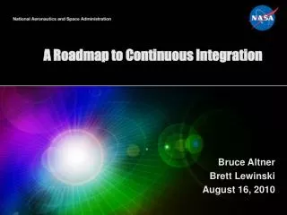
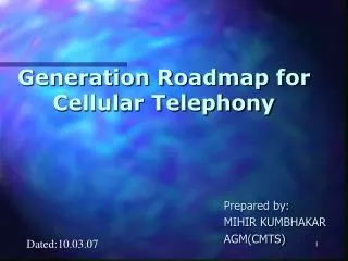
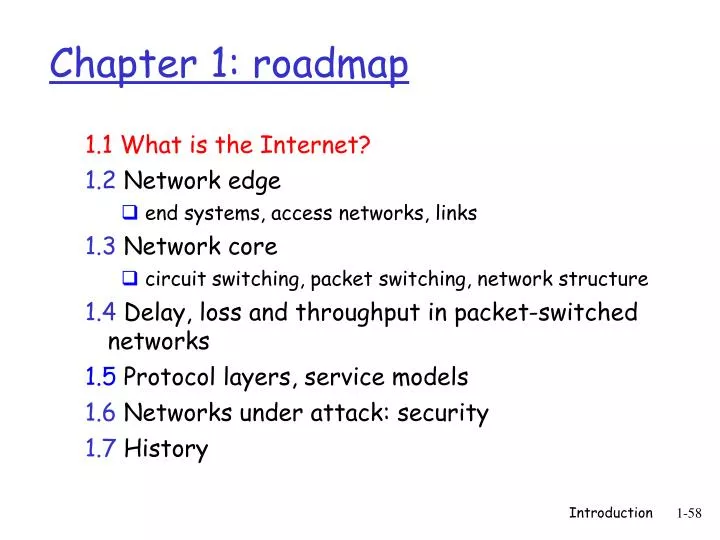
Chapter 1: roadmap. 1.1 What is the Internet? 1.2 Network edge end systems, access networks, links 1.3 Network core circuit switching, packet switching, network structure 1.4 Delay, loss and throughput in packet-switched networks 1.5 Protocol layers, service models

E N D
Chapter 1: roadmap 1.1 What is the Internet? 1.2 Network edge • end systems, access networks, links 1.3 Network core • circuit switching, packet switching, network structure 1.4 Delay, loss and throughput in packet-switched networks 1.5 Protocol layers, service models 1.6 Networks under attack: security 1.7 History Introduction 1-58
Mobile network PC What’s the Internet: “nuts and bolts” view access points router server Global ISP wired links wireless laptop cellular handheld Home network Regional ISP Institutional network • millions of connected computing devices: hosts = end systems • running network apps • communication links • fiber, copper, radio, satellite • transmission rate = bandwidth • routers: forward packets (chunks of data) Introduction 1-59
Mobile network What’s the Internet: “nuts and bolts” view Global ISP Home network Regional ISP Institutional network • protocols control sending, receiving of msgs • e.g., TCP, IP, HTTP, Skype, Ethernet • Internet: “network of networks” • loosely hierarchical • public Internet versus private intranet • Internet standards • RFC: Request for comments • IETF: Internet Engineering Task Force Introduction 1-61
What’s the Internet: a service view • communication infrastructure enables distributed applications: • Web, VoIP, email, games, e-commerce, file sharing • communication services provided to apps: • reliable data delivery from source to destination • “best effort” (unreliable) data delivery Introduction 1-62
2: Application Layer e-mail web instant messaging remote login P2P file sharing multi-user network games streaming stored video clips social networks voice over IP real-time video conferencing grid computing Some network apps
What’s a protocol? • network protocols: • machines rather than humans • all communication activity in Internet governed by protocols human protocols: • “what’s the time?” • “I have a question” • introductions … specific msgs sent … specific actions taken when msgs received, or other events protocols define format, order of msgs sent and received among network entities, and actions taken on msg transmission, receipt Introduction 1-63
Got the time? 2:00 TCP connection response Get http://www.awl.com/kurose-ross <file> time What’s a protocol? a human protocol and a computer network protocol: Hi TCP connection request Hi Q: Other human protocols? Introduction 1-64
A closer look at network structure: • network edge: applications and hosts • access networks, physical media: wired, wireless communication links • network core: • interconnected routers • network of networks Introduction 1-66
Packet vs. circuit switching • mesh of interconnected routers • the fundamental question: how is data transferred through net? • circuit switching: dedicated circuit per call: telephone net • packet-switching: data sent thru net in discrete “chunks” Introduction 1-4
Case study: Circuit Switching • 1890-current: Phone network • Fixed bit rate • Mostly voice • Not fault-tolerant • Components extremely reliable • Global application-level knowledge throughout network Introduction 1-5
Case study: Packet Switching • 1981-current: Internet network • Variable bit rate • Mostly data • Fault-tolerant • Components not extremely reliable (versus phone components) • Distributed control and management Introduction 1-6
Circuit Switching End-end resources reserved for “call” • network resources (e.g., bandwidth) divided into “pieces” • link bandwidth, switch capacity • pieces allocated to calls • resource piece idle if not used by owning call • dedicated resources: no sharing • circuit-like (guaranteed) performance • call setup and admission control required Introduction 1-7
FDM TDM 4 users Example: Circuit Switching: FDM and TDM frequency frequency time time Introduction 1-8
Network Core: Packet Switching Bandwidth division into “pieces” Dedicated allocation Resource reservation • resource contention: • aggregate resource demand can exceed amount available • congestion: packets queue, wait for link use • store and forward: packets move one hop at a time • Node receives complete packet before forwarding each end-end data stream divided into packets • user A, B packets share network resources • each packet uses full link bandwidth • resources used as needed Introduction 1-10
Packet Switching: Statistical Multiplexing D E 10 Mb/s Ethernet C A Sequence of A & B packets does not have fixed pattern, shared on demand è statistical multiplexing. TDM: each host gets same slot in revolving TDM frame. statistical multiplexing 1.5 Mb/s B queue of packets waiting for output link Introduction 1-11
Packet switching versus circuit switching Packet switching allows more users to use network! • N users over 1 Mb/s link • each user: • 100 kb/s when “active” • active 10% of time • circuit-switching: • 10 users • packet switching: • with 35 users, probability > 10 active less than .0004 • Allows more users to use network • “Statistical multiplexing gain” N users 1 Mbps link Q: how did we get value 0.0004? Introduction 1-12
Packet switching versus circuit switching Is packet switching a “slam dunk winner?” • Great for bursty data • resource sharing • simpler, no call setup • Bad for applications with hard resource requirements • Excessive congestion: packet delay and loss • Need protocols for reliable data transfer, congestion control • Applications must be written to handle congestion • Q: How to provide circuit-like behavior? • bandwidth guarantees needed for audio/video apps • still an unsolved problem Introduction 1-13
How do loss and delay occur? packets queueing (delay) free (available) buffers: arriving packets dropped (loss) if no free buffers packets queue in router buffers • packet arrival rate to link exceeds output link capacity • packets queue, wait for turn • when packet arrives to full queue, packet is dropped (aka lost) • lost packet may be retransmitted by previous node, by source end system, or not retransmitted at all packet being transmitted (delay) A B Introduction 1-14
transmission Four sources of packet delay A propagation B nodal processing queueing • 1. nodal processing: • check bit errors • determine output link • 2. queueing • time waiting at output link for transmission • depends on congestion level of router Introduction 1-15
transmission Delay in packet-switched networks A propagation B nodal processing queueing • 4. Propagation delay: • d = length of physical link • s = propagation speed in medium (~2x10⁸ m/sec) • propagation delay = d/s 3. Transmission delay: • R=link bandwidth (bps) • L=packet length (bits) • time to send bits into link = L/R Note: s and R are very different quantities! Introduction 1-16
Nodal delay • dproc = processing delay • typically a few microsecs or less • dqueue = queuing delay • depends on congestion • dtrans = transmission delay • = L/R, significant for low-speed links • dprop = propagation delay • a few microsecs to hundreds of msecs Introduction 1-17
Queueing delay (revisited) • R=link bandwidth (bps) • L=packet length (bits) • a=average packet arrival rate traffic intensity = La/R • La/R ~ 0: average queueing delay small • La/R -> 1: delays become large • La/R > 1: more “work” arriving than can be serviced, average delay infinite! Introduction 1-18
L Transmission delay • Packet switching • Store-and-forward • Packet completely received before being transmitted to next node • Takes L/R seconds to transmit (push out) packet of L bits on to link or R bps • Entire packet must arrive at router before it can be transmitted on next link: store and forward • delay = 3L/R (assuming zero propagation delay) R R R • Example: • L = 7.5 Mbits • R = 1.5 Mbps • delay = 15 sec more on delay shortly … Introduction 1-19
“Real” Internet delays and routes • What do “real” Internet delay & loss look like? • Traceroute program: provides delay measurement from source to router along end-end Internet path towards destination. For all i: • sends three packets that will reach router i on path towards destination • router i will return packets to sender • sender times interval between transmission and reply. 3 probes 3 probes 3 probes Introduction 1-20
“Real” Internet delays and routes traceroute: gaia.cs.umass.edu to www.eurecom.fr Three delay measurements from gaia.cs.umass.edu to cs-gw.cs.umass.edu 1 cs-gw (128.119.240.254) 1 ms 1 ms 2 ms 2 border1-rt-fa5-1-0.gw.umass.edu (128.119.3.145) 1 ms 1 ms 2 ms 3 cht-vbns.gw.umass.edu (128.119.3.130) 6 ms 5 ms 5 ms 4 jn1-at1-0-0-19.wor.vbns.net (204.147.132.129) 16 ms 11 ms 13 ms 5 jn1-so7-0-0-0.wae.vbns.net (204.147.136.136) 21 ms 18 ms 18 ms 6 abilene-vbns.abilene.ucaid.edu (198.32.11.9) 22 ms 18 ms 22 ms 7 nycm-wash.abilene.ucaid.edu (198.32.8.46) 22 ms 22 ms 22 ms 8 62.40.103.253 (62.40.103.253) 104 ms 109 ms 106 ms 9 de2-1.de1.de.geant.net (62.40.96.129) 109 ms 102 ms 104 ms 10 de.fr1.fr.geant.net (62.40.96.50) 113 ms 121 ms 114 ms 11 renater-gw.fr1.fr.geant.net (62.40.103.54) 112 ms 114 ms 112 ms 12 nio-n2.cssi.renater.fr (193.51.206.13) 111 ms 114 ms 116 ms 13 nice.cssi.renater.fr (195.220.98.102) 123 ms 125 ms 124 ms 14 r3t2-nice.cssi.renater.fr (195.220.98.110) 126 ms 126 ms 124 ms 15 eurecom-valbonne.r3t2.ft.net (193.48.50.54) 135 ms 128 ms 133 ms 16 194.214.211.25 (194.214.211.25) 126 ms 128 ms 126 ms 17 * * * 18 * * * 19 fantasia.eurecom.fr (193.55.113.142) 132 ms 128 ms 136ms trans-oceanic link * means no response (probe lost, router not replying) Introduction 1-21
Packet loss • queue (aka buffer) preceding link in buffer has finite capacity • packet arriving to full queue dropped (aka lost) • lost packet may be retransmitted by previous node, by source end system, or not at all buffer (waiting area) packet being transmitted A B packet arriving to full bufferis lost Introduction 1-110
pipe that can carry fluid at rate Rsbits/sec) pipe that can carry fluid at rate Rcbits/sec) server sends bits (fluid) into pipe Throughput • throughput: rate (bits/time unit) at which bits transferred between sender/receiver • instantaneous: rate at given point in time • average: rate over longer period of time link capacity Rcbits/sec link capacity Rsbits/sec server, with file of F bits to send to client Introduction 1-111
Rs > RcWhat is average end-end throughput? bottleneck link Throughput (more) Rcbits/sec link on end-end path that constrains end-end throughput Rsbits/sec Rcbits/sec • Rs < RcWhat is average end-end throughput? Rsbits/sec Introduction 1-112
Throughput: Internet scenario • per-connection end-end throughput: min(Rc,Rs,R/10) • in practice: Rc or Rs is often bottleneck Rs Rs Rs R Rc Rc Rc 10 connections (fairly) share backbone bottleneck link Rbits/sec Introduction 1-113
Why layering? Dealing with complex systems: • explicit structure allows identification, relationship of complex system’s pieces • layered reference model for discussion • modularization eases maintenance, updating of system • change of implementation of layer’s service transparent to rest of system • e.g., change in gate procedure doesn’t affect rest of system • layering considered harmful? Introduction 1-118
Layering • Modular approach to network functionality • Simplifies complex systems • Each layer relies on services from layer below and exports services to layer above • Hides implementation, eases maintenance and updating of system • Layer implementations can change without disturbing other layers (black box) Introduction 1-35
Layering Application Link hardware Host-to-host connectivity • Examples: • Topology and physical configuration hidden by network-layer routing • Applications require no knowledge of this • New applications deployed without coordination with network operators or operating system vendors Introduction 1-36
Layering in Protocols • Set of rules governing communication between network elements (applications, hosts, routers) • Protocols specify: • Interface to higher layers (API) • Interface to peer • Format and order of messages • Actions taken on receipt of a message • Interface defines interaction Introduction 1-37
Internet protocol stack application transport network link physical • application: supporting network applications • FTP, SMTP, HTTP • transport: process-process data transfer • TCP, UDP • network: routing of datagrams from source to destination • IP, routing protocols • link: data transfer between neighboring network elements • PPP, Ethernet • physical: bits “on the wire” Introduction 1-119
Layering in Networks: OSI Model Application Presentation Session Transport Network Data Link Physical Host • Physical • how to transmit bits • Data link • how to transmit frames • Network • how to route packets host-to-host • Transport • how to send packets end2end • Session • how to tie flows together • Presentation • byte ordering, formatting • Application: everything else Introduction 1-38
Hl Hl Hl Hl Hl Hl Ht Ht Hn Hn Hn Hn Hn Hn Hn Hn Hn Hn Ht Ht Ht Ht Ht Ht Ht Ht Ht Ht Encapsulation M M link physical network link physical M M M M M M M M M M M M source message application transport network link physical segment datagram frame switch destination application transport network link physical router Introduction 1-39
Distributed design and control • Requirements from DARPA • Must survive a nuclear attack • Reliability • Intelligent aggregation of unreliable components • Alternate paths, adaptivity • Distributed management & control of networks • Exceptions: TLDs and TLD servers, IP address allocation (ICANN) Back Introduction 1-40
Superior organizational process • IAB/IETF process allowed for quick specification, implementation, and deployment of new standards • Free and easy download of standards • Rough consensus and running code • 2 interoperable implementations • Bake-offs • http://www.ietf.org/ • ISO/OSI • Comparison to IETF left as an exercise Back Introduction 1-41
A day in the life of an Internet host… • Booting • Dynamically configure network settings • DHCP, BOOTP request • UDP (unreliable datagrams) • IP and data-link broadcast • DHCP, BOOTP response from listening server • IP address of host, DNS server, and default router • Netmask (i.e. 255.255.255.0) to determine network ID Introduction 1-42
A day in the life of an Internet host… • Web request http://www.yahoo.com/index.html • Step #1: Locate DNS server if (netmask & IPHost == netmask & IPDNS) DNS server on local network ARP for hardware address of IPDNS else DNS server on remote network ARP for hardware address of IPDefaultRouter • ARP (Address Resolution Protocol) • IP address to hardware address mapping • Request broadcast for all hosts on network to see • Reply broadcast for all hosts to cache Introduction 1-43
A day in the life of an Internet host… • Step #2: ARP request and reply Introduction 1-44
A day in the life of an Internet host… Datalink header DNS reply IP of host UDP Header (host) www.yahoo.com is 216.115.105.2 • Step #2: DNS request and reply • UDP, IP, data-link header Introduction 1-45
A day in the life of an Internet host… Datalink header HTTP reply IP of host TCP Header HTTP/1.0 200 OK (host) Date: Mon, 24 Sep 2001 Content - Type: text/html <HTML> etc… • Step #3: TCP connection establishment + HTTP request and reply • HTTP (application data) “GET index.html” “HTTP/1.0” • TCP (session establishment, reliable byte stream) • IP, data-link header Introduction 1-46
A day in the life of an Internet host… NETn NET2 NET1 FTP HTTP NV TCP TFTP IPX … IP UDP Network TCP/UDP IP • Role of TCP and UDP? • Demultiplex at end hosts. • Which process gets this request? Type Field Protocol Field Port Number Introduction 1-47
A day in the life of an Internet host…. • What about…. • Reliability • Corruption • Lost packets • Flow and congestion control • Fragmentation • Out-of-order delivery • The beauty of TCP, IP, and layering • All taken care of transparently Introduction 1-48