Download
1 / 10
140 likes | 370 Views
Geometric Dimensioning and Tolerancing. Chapter 8, Tolerances of Location. Geometric Characteristics. Form, Orientation, Profile, and Runout Tolerances. In Chapter 6, we discussed the geometric characteristics highlighted above. Geometric Characteristics.

E N D
Geometric Dimensioning and Tolerancing Chapter 8, Tolerances of Location
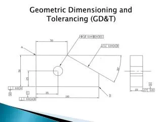
Geometric Characteristics Form, Orientation, Profile, and Runout Tolerances In Chapter 6, we discussed the geometric characteristics highlighted above.
Geometric Characteristics Form, Orientation, Profile, and Runout Tolerances In Chapter 8, we will now discuss the location tolerances.
Concentricity • Used to establish a tolerance zone for the median points of a cylindrical feature. • The FCF reads,"relativeto datum A, all median points of opposing elements on thiscylindrical surface must liewithin a cylindrical tolerancezone of 0.5 mm".
Symmetry • Symmetry is the condition where a feature or part has the same profile on either side of the center plane (median plane) of a datum feature. • The controlled feature is permitted a maximum of .005 inch shift to the side in either direction.
Position Tolerance • Position is one of the most effective and used controls in GD&T. • Position is defined in terms of feature centers. • The tolerance zone may be modified with the geometric modifiers, i.e. MMC, LMC, or RFS.
Position Tolerance • The ‘perfect’ location of the center of the hole relative to the datums is defined by basic dimensions.
Position Tolerance • If the hole is made at MMC ( .528), the center position must lie within a cylindrical tolerance zone of diameter .010.
Position Tolerance • If you make the hole diameter at a size different than MMC, you will be given a larger position tolerance size.
Position Tolerance • When are the MMC, LMC, and RFS used for position tolerance? • Let’s see ‘How it Works”.