Download

1 / 41
420 likes | 616 Views
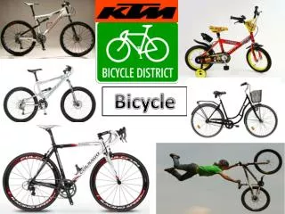
POV Bicycle. Group 29 Matthew Egan Sean Schindzielorz Gian Thomas Nancy Zanaty . Background . Persistence of vision to create optical illusions Lights spinning at rapid, consistent pace form images Using bicycle wheels and LEDs to produce images using POV . Project Overview .

E N D
POV Bicycle Group 29 Matthew Egan Sean Schindzielorz Gian Thomas Nancy Zanaty
Background • Persistence of vision to create optical illusions • Lights spinning at rapid, consistent pace form images • Using bicycle wheels and LEDs to produce images using POV
Project Overview • Bicycle with wireless transceiver to which user can transmit images • Bicycle receives and processes images, delivers to LED display on wheel • When bicycle wheels are rotating due to pedaling, images are formed from the LEDs • Can charge your phone!
Objectives • Mobility: The system must be light enough not to affect the usability of the bike. It should also be self contained to avoid tangling cables. The electronics should be weather resistant. • Endurance: The system must be capable of displaying a message for an extended period of time without recharging because the intended purpose of this project is as a mobile billboard. • Range: The system should allow for remote uploading of images and text to the display so the bike does not need to be manually connected to a PC to change messages. • Compatibility: The client software must be compatible with a common office computer and user friendly.
LEDs • Small size to eliminate streaking- 5mm • RGB for color mixing • Small driving current (~20mA) • Common anode
Hall Effect Sensor • OPTEK Technology OH090U • Acts as Reed Switch • In presence of magnetic field it switches LOW
7-Segment Display • LCDs, CRTS, and Plasma displays were all briefly considered for use on the handle bar display, but a 7-segment suits the role best. • 7-segments are very low power, very low cost easily visible in direct sunlight, and easy to implement.
Power- Generator • Pedal Operated Generator produces power as you ride • Charges the secondary battery.
AC to DC Charger • Regulated DC voltage • High output current about 2.5A • No transformer.
Switching Voltage Regulator • 3V to 25V operating range • High switching efficiency and frequency • 0.5-3A output current • 1.8-5V output Voltage • Thermal Shutdown
Image Scaling Algorithms Nearest Neighbor Scaling: • Produces a new image by creating a scaled up array and filling the blank spaces with the same color values as their nearest neighbors. • It’s fast but produces VERY jagged ugly images.
Image Scaling Algorithms (Continued) Bilinear Interpolation: • Functions similarly to nearest neighbor, but instead of copying neighbors to obtain color values, the neighbors are averaged. Bilinear Interpolation does this average in both the x and y direction for each missing pixel. • Produces relatively sharp images quickly. Linear Interpolation Example: Pixel Y is defined as the weighted average of it’s two nearest neighbors, A and B:
Image Scaling Algorithms (Continued) Trilinear Interpolation: • Modified form of bilinear scaling. It results in an even sharper image, takes a lot of time. Since the display has so few LEDs, this was overkill.
Radial Image Conversion • After scaling the normally rectangular images will be split into n polar arrays, by using the equation of a line through the center of the image. Each array will have 16 slots, each corresponding to an LED. • When the line doesn’t cut cleanly, the pixels will be averaged using linear interpolation.
Primary Microcontroller • OBJECTIVES: • Receive Bluetooth Data • Receive Sensor Data • Control TLC5940
Software – LED Array • TLC5940
Software – LED Array FOR EACH BIT SET PIN1.1 = (1 or 0) PULSE PIN 1.2 DO THIS 4098 TIMES PULSE PIN 1.3 SET PIN 1.4 HIGH PULSE PIN 1.0 SET PIN 1.4 LOW
Secondary Micrcontroller Wheel rotation, in RPM, will be measured using Hall Effect sensors, mounted on the wheel. The following will be calculated and displayed: Velocity(Km/h) = Wheel Circumference(m) *60/1000 Distance(Km) = Revolutions*Wheel Circumference(m)/1000 An analog to digital converter will measure the voltage across a small resistive load. The estimated remaining battery life is then: % Charge = VLoad/VBattery