Download
1 / 26
270 likes | 696 Views
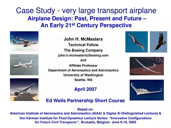
Case Study - very large transport airplane Airplane Design: Past, Present and Future – An Early 21 st Century Perspective. Affiliate Professor Department of Aeronautics and Astronautics University of Washington Seattle, WA. John H. McMasters Technical Fellow The Boeing Company

E N D
Case Study - very large transport airplane Airplane Design: Past, Present and Future – An Early 21st Century Perspective Affiliate Professor Department of Aeronautics and Astronautics University of Washington Seattle, WA John H. McMasters Technical Fellow The Boeing Company john.h.mcmasters@boeing.com and April 2007 Ed Wells Partnership Short Course Based on: American Institute of Aeronautics and Astronautics (AIAA) & Sigma Xi Distinguished Lectures & Von Kármán Institute for Fluid Dynamics Lecture Series: “Innovative Configurations for Future Civil Transports”, Brussels, Belgium June 6-10, 2005
A Area (ft.2, m2) a Speed of sound (ft./sec., m/s) AR Aspect ratio, b/č = b2/S b Wing span (ft., m) č Average wing chord (ft.,m) CF Force coefficients (lift, drag, etc.) = F/qS Cℓ Section (2D) lift coefficient CM Moment coefficient = M/qSĉ Cp Pressure coefficient = Δp/q D Drag force (lb., N) E Energy (Ft.-lbs., N-m) e “Oswald efficency factor” ew Wing span efficiency factor (= 1/kw ) F Force (lift, drag, etc.) (lbs., N) H Total head (reservoir pressure) I Moment of inertia kw Wing span efficiency factor (= 1/ew) L Lift force (lb., N) ℓ Length (ft., m) M Mach number (V/a) M Mass (kg) M Moment (ft. lbs., N m) P Power (ft.-lbs./sec., N-m/sec.) p Static pressure (lbs./ft.2) q Dynamic pressure (lbs./ft.2) = ½ρV2 R Range (mi., km) Rn Reynolds number (ρVℓ / μ) S Wing area (ft.2, m2) T Thrust (lb., N) T Temperature (oF) u Local x-direction velocity component V Velocity, Speed (ft./sec., m/s, mph, km/h) v Local y-direction velocity component w Downwash velocity (ft./sec., m/s) ż Sink rate (vertical velocity) (ft./sec., m/s) Greek: α Angle of attack (deg.) Γ Circulation γ Climb or glide angle (deg., rad.) γ Ratio of specific heats in a fluid ε Wing twist angle (deg.) θ Downwash angle (deg.) φ Velocity potential Λ Wing sweep angle (deg.) μ Dynamic viscosity ν Kinematic viscosity (μ/ρ) ρ Fluid mass density (kg/m3) Notation and Symbols Used
Presentation Overview • Case Studies • II. “Very large” transport airplanes (A380s, flying wings and C-wings)
Case II. The “Big Airplane” Problem Antonov An 225 “Mriya” Wing Span: 290 ft. (88.4 m) MTOW: 1,322,750 lb. (600,000 kg) Six 51,590 lb. ST (23,400 kgp) Lotarev D-18T turbofans
Boeing Product Development Opportunities (circa 1990) In Production Development or Study
Typical Marketing “Range-Payload” Diagram (Market Niches –Product Development Opportunities – circa 1985-90) NLA 777 Seats 7J7 Range (nmi.)
Air Traffic Growth and Aircraft Arrival/Departure Data for Kennedy International Airport (to circa 1995) Passengers Per Year (millions) Aircraft Per Year (thousands) Aircraft Passengers 15 10 85 70 5 0 55 Advent of Wide-Body Transports (B 747, DC-10, L 1011, etc.) 40 1960 1970 1980 1990 2000 Year
Wake Vortex Separation Standards Heavy (H) Airplanes over 300,00 lb. max. certified take-off weight (MCTOW) (e.g. B777, B767, B747, MD 11) Medium (M) Airplanes with MCTOW between 15,400 and 300,000 lbs. Light (L) Airplanes with MCTOW less than 15,400 lbs. Radar Separation: Time Separation: Heavy behind Heavy 4 n. mi. Medium behind Heavy 2 min. Medium behind Heavy 5 n. mi. Light behind Heavy 3 min. Light behind A38010 n. mi. Light behind Heavy 6 n. mi. Light behind Medium 5 n. mi.
“Square-Cube Law” Trends in Size & DOC (Conventional “Tube and Wing” Configurations) Direct Operating Cost (cents/seat-mi.) Wing Span (ft.) ~ 600 Passengers Passengers Thanks to Ilan kroo
Classic Configuration Evolution 600+ passengers ~140 passengers Super 747 (NLA) 707-120 Too long to fit in terminal gates, so.. 7?7 (NLA) 747-400 Outboard engines at wing tip stations of a 747 ~ 425 passengers
Airbus A380 Jumbo Jumbo-Jet Goodyear
Jumbo 600 Passenger Subsonic Transport (circa 1992) • Configuration Issues: • Runway limits • Taxiway limits • Terminal gate limits • Emergency • evacuation • Community noise • Wake vortices • Wing skin size • limits • Ditching/flotation • Passenger • comfort Must fit within a 80 m box
Northrop B-49 bomber (circa 1948-49) Northrop Grumman B-2
Early Attempts to Solve the “Large [600+ Passenger]Transport Airplane Problem” McMasters/Boeing Conceptual “747 XXL” circa 1992 An Early Version of the Liebeck Blended Wing-Body Subsonic Transport Wing Spans b ≈ 300 ft. Griffith airfoil From the desk of J. H. McMasters, 1992
The Griffith Airfoil (circa 1944) Favorable gradient for laminar flow - Pressure recovery (turbulent flow) CP ć 0 c t Conventional airfoil (chord ć ) Suction slot + Griffith airfoil (chord c ) 1 Transonic Griffith airfoil
A Flawed (and Clumsy) Attempt to Emulate Nature http://www.winggrid.ch/index.htm
A Family of Non-Planar Wing ConfigurationsConstant wing span (b), area (S) and height-to-span ratio [ h/b=0.2 ] Total Drag (D) = Dviscous + Dinduced [+ Dcompressibility ] Dviscous ~ SwetV2f(CL) Induced Drag (drag due to lift) = Di ~ kw [Lift (L)/span (b)]2x speed (V)-2 ~ kw [W/b] 2 kw = theoretical wing span efficiency factor = 1/ewIn steady, level flight, Lift (L) = Weight (W) b Biplane kw = 0.74 X-wing kw = 0.75 Branched tips kw = 0.76 (“pfeathers”) Tip plates kw = 0.72 Box biplane kw = 0.68 Joined wing kw = 0.95 C-Wing kw = 0.69 Tip plated winglets kw = 0.83 Winglets kw = 0.71 Dihedral kw = 0.97 h Note: For an optimally loaded planar wing of the same span and area kw = 1.0 Aspect ratio = b2S Treffetz plane analyses due to Prof. Ilan Kroo, Stanford University (circa 1992).
Non-Planar Wing Span Loads L/2 Planar Wing L/2 L/2 Winglets L/2 L1 L1 L/2 + L2 C-Wing L1 L/2 L2 L1 L2 h b/2 b/2 h Winglet-let
A Possible [Slightly Grotesque] C-Wing Large Transport Airplane Configuration Baseline Baseline Configuration From the desk of J.H. McMasters, 1994
600+ Passenger C-Wing Transport Configuration(Semi-Span Loader, Quasi-Three-Surface Airplanes) Boeing configuration patent granted 1996. McMasters, J.H. and Kroo, I. M., “Advanced Configurations for Very Large Subsonic Transport Airplanes”, NASA CR 198351, Oct. 1996; also Aircraft Design, Vol. 1, No. 4, 1998, pp. 217-242.
Layout of Passenger Accommodations (LOPA) for a Single Deck, 3-Class, 600 Passenger C-Wing Transport
Size Comparison for a Conventional and C-Wing 600 Passenger Transport Airplane
Some Configuration Options For Very Large Commercial Transport Airplanes “Transonic Seagull” “Winged Watermelon” (“Flying Spud”) “Klingon Battle Cruiser” A “Smart” C-Wing BWB ? 2 or more “small” airplanes In formation ?
Smart Wings • Analogies • Pterosaur Airplane • Brain Computer • Nerves Fiber optic strain • gages, pressure • sensors • Bone and tissue Composite materials • Variable geometry Electro-mechanical • control via large control of large • and small muscles and small aerodynamic • devices distributed over • wing trailing edge • Potential Benefits • Reduced wing weight for a given wing • span • Increased span (reduced drag) for wing of • given weight • May enable the use of highly non-planar • wing configurations (e.g. C-wings) Inputs from nerves distributed throughout the living tissue of the wing membrane Control output to muscles throughout wing membrane Ultra light weight structure (strong but highly flexible) Kroo MITEs (digitized, segmented Gurney flaps) Brain highly modified to process sensory data and provide needed control output