Download

1 / 27
290 likes | 723 Views
Aircraft Familiarization Deputy Chief Rick Wilson. Boeing 737. Objectives. To familiarize personnel with identification characteristics of the Boeing 737 type aircraft. To review the engine, auxiliary power unit (A.P.U.), hydraulic, and shutdown procedures on the aircraft.

E N D
Objectives • To familiarize personnel with identification characteristics of the Boeing 737 type aircraft. • To review the engine, auxiliary power unit (A.P.U.), hydraulic, and shutdown procedures on the aircraft. • To review egress possibilities on the aircraft.
Identifying Characteristics • 1 main cabin door 3 service doors located fore and aft • 2 cargo doors on the lower right hand side located fore and aft of the wing root.
Identifying Characteristics 737-300 CFM563B1 turbofans Aircraft sits very low to the ground (engines are only 1’-6” off the ground)
Characteristics 737-300 • Length – 109’-7” • Width – 94’-9” • Height – 26’-6” • Seating Cap.– 128 • Fuel – Jet A • Power Plants: CFM563B1 turbofans
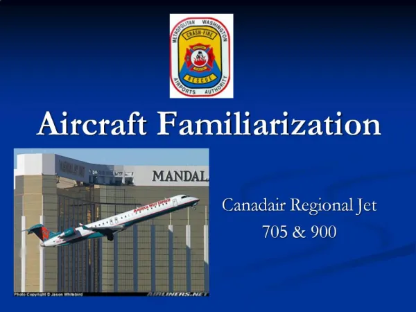
Characteristics 737-900 • Length – 138’-2” • Width – 117’-5” • Height – 41’-3” • Seating Cap.– 177 • Fuel – Jet A • Power Plants: 117kN (26,300lb) CFM56-7B26s
Danger Areas • Landing gear • Approach wheel/tire from Fore or Aft • Use caution being directly in line with the tires. (This may expose crews dangerous conditions if tires were to explode) • Approaching from the side may expose the crews to shrapnel from a wheel explosion • Wheels are equipped with fusible plugs designed to melt and deflate the tire when temperature is excessive
Danger Areas Engine intakes/exhausts • Maintain 30 foot radius from the intake (front) of the engines while the engines are running • Maintain 1000 foot distance from the exhaust (rear) of the engines while the engines are running • APU-Hot exhaust and air intake hazards
Danger Areas Materials used in construction Aluminum and Aluminum Alloys Steel Magnesium and Magnesium Alloys Titanium Composite Materials
Danger Areas Cargo Caution should be used when dealing with any cargo onboard aircraft for unknown and possibly hazardous substances Cargo doors are located fore and aft on the pilots right side. Cargo areas are protected by an extinguishing system use caution when the system has been activated.
Capacities • Fuel • Type-Jet A • Quantity 6,295 Gallons • 1499 gallons Located in each wing tank • 2313 gallons located in the center fuselage tank • Note amounts may vary based on configuration and series • Quantities listed represent 737 300-400
Systems • Oxygen • Cockpit supply bottle • Oxygen generator system. Each group of passenger seats will have a inert but electrically activated • Hydraulic • Operating pressure of 3,000 psi. • Hydraulic fluid reservoir located in each wheel well.
Electrical System • Electrical • Consists of two nickel cadmium batteries • Main batteries are located in the electronic equipment (E&E) compartment which is located Aft of the nose gear • To disconnect use a quarter turn quick disconnect
Shutdown Procedures-Batteries • Master switch is located on the left hand side of the overhead console • Move switch to the “Off” position
Electrical System-A.P.U. • A.P.U.-located in the tail section • The internal APU control panel is located on the overhead console • The external shutdown is located The control panel is located inside the Main Landing gear well area, aft bulkhead.
Electrical System-A.P.U. • External operation • TO SHUTDOWN AN OPERATING APU: • 1. Lift guard on "APU STOP" switch. • 2. Place switch to "OFF" position. APU will shutdown. NOTE: If Electrical Power or Pneumatic pressure for Air Conditioning was being supplied by the APUs, those functions will be lost.
Electrical System-A.P.U. • Internal fire operation • Switch APU stop switch to “APU off” position 1. Identify the APU Fire Control Panel located on the center of the aircraft's Fire Control Panel, forward section of the lower control console, between the pilots seats. 2. Upon identification, locate the APU Fire "T" handle. 3. PULL/LIFT the illuminated "T" handle. This action will shutoff fuel to the APU, and arm the agent discharge circuit. 4. ROTATE/TWIST the pulled handle either Clockwise or counterclockwise to discharge the single Fire Bottle.
Electrical System-A.P.U. • External fire operation • Switch APU stop switch to “APU off” position 1. Identify and Locate the APU Fire "T" handle on the Remote APU Control Panel . This handle will be an "inverted T". 2. Pull this handle DOWN. This action will shutdown an operating APU and arm the agent discharge system. 3. Move the spring loaded "Bottle Discharge" switch, to DISCHARGE. This action will discharge the single APU Fire Bottle.
Shutdown Procedures-Engines • Internal • Engine shutdown “T” handle • Located on the center console, • The “T” handle will illuminate red if there is an indication of fire
Shutdown Procedures-Engines • Engine shutdown “T” handle procedures 1.Identify the Engine Fire Control Panel, located on the lower center console, between the pilot seats. 2. Upon identification, locate the illuminated Engine Fire"T" handle. 3. Upon identification, LIFT/PULL the alarming "T" handle UP. This action will close all fuel valves to that engine, and arm the agent discharge circuits. 4. ROTATE/TWIST the handle clockwise or counter clock-wise to discharge the agent. This is confirmed by the respective agent discharge light illuminating. 5. If the Fire Warning continues, ROTATE the handle in the opposite direction, to discharge the remaining bottle.
Egress-Doors • Doors-2 main doors per side of aircraft • Sill height • Wheels extended=8’-6” • Wheels retracted=5” • Operation • Main cabin door • Pull handle from recess • Rotate handle Clockwise • Fore and Aft service doors rotate counter clockwise • Pull door open • Slides-are installed on main cabin doors
Egress-Windows • Windows-One or two over-wing exit hatches each side (depending on model) • Operation • From Inside • push in panel at the top of the hatch while pulling hatch inward • From Outside • Pull Handle Release • Pull Handle and at the same time push in top of door forcibly
Egress- RT Cockpit Window To assist in cockpit escape, or to gain entry into the cockpit: 1. Gain access to the right hand side of the cockpit adjacent to, and facing the sliding (side) window. 2. Identify the PUSH/PULL placard below the side window. 3. PUSH IN and GRASP the window release handle. 4. PULL the window release handle OUT. This action will unlock the sliding window, and move it inboard. 5. PUSH the window IN and GRASPING the forward edge PUSH/SLIDE the window assembly AFT.
Summary • This lesson should give you a basic familiarization with the Boeing 737 aircraft • This knowledge should be backed up by going aboard a 737 to actually operate cabin doors, locate important systems, and familiarize personnel with the aircraft. • For more information contact other shift personnel, officers, or training division personnel.
References • Boeing Aircraft Rescue and Fire fighting Information • ASAP • Airliners.com • Sandpiper Group Aircraft Crash Recovery Guide • USAF T.O. 105E-9