Download
1 / 58
590 likes | 810 Views
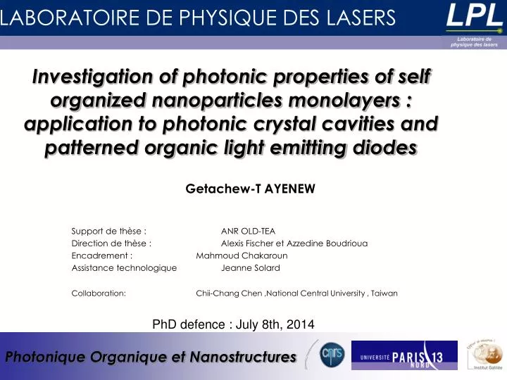
Investigation of photonic properties of self organized nanoparticles monolayers : application to photonic crystal cavities and patterned organic light emitting diodes. Getachew-T AYENEW. Support de thèse : ANR OLD-TEA

E N D
Investigation of photonic properties of self organized nanoparticles monolayers : application to photonic crystal cavities and patterned organic light emitting diodes Getachew-T AYENEW Support de thèse : ANR OLD-TEA Direction de thèse : Alexis Fischer et Azzedine Boudrioua Encadrement : Mahmoud Chakaroun Assistance technologique Jeanne Solard Collaboration: Chii-Chang Chen ,National Central University , Taiwan PhD defence : July 8th, 2014
Outline • Introduction • Context • State of the art • Our approach • Photonic properties of monolayer of opals and inverse-opals • Numerical study of photonic band gaps • Numerical study of microcavities • Experimental approach of characterizing monolayer of opals • Nanoparticle based 2D patterning of OLED • 2D pattering of surfaces • 2D patterning of OLEDs • Conclusion and perspectives 2
1. Introduction Context :ANR OLD-TEA 2010-2013 Organic Laser Diode : A Threshold-Less Experimental Approach Axe 1 Axe 2 1D Vertical confinement 2D lateral confinement Top down Bottom up Small Mode volume High Q Photonic Crystal Opals - Inverse Opals Extended cavity Potential Applications Low threshold organic diode laser 2D DFB lasers Light extraction in OLED 3
1. Introduction Objectives of the study Self-organized Nanoparticles Photonic crystals OLED Nanostructuration Photonic crystal laser with defect microcavity 2D-DFB OLD Light extraction in OLED • Photonic properties of monolayer of nanoparticles and microcavities • New patterning technique using nanoparticles 4
1. Introduction Objectives of the study Self-organized Nanoparticles Photonic crystals OLED Nanostructuration Photonic crystal laser with defect microcavity 2D-DFB OLD Light extraction in OLED • Photonic properties of monolayer of nanoparticles and microcavities • Making nanostructures using nanoparticles 5
2. Photonic properties of monolayer of opals and inverse-opals State of the art Polymeric solid-state dye lasers resonator highly-efficientlow threshold laser Emission spectra of the resonator cavity below and above lasing threshold Shi et al. Appl. Phys. Lett. 98, 093304 (2011) Dye doped photonic crystal Random lasing Kim et al Chem. Mater., 2009, 21 (20), pp 4993–4999 Murai et al, Chemistry LettersVol. 39 (2010) , No. 6 p.532 • Lasing by randomly dispersing nanoparticles into a gain material • multiple scattering • porous photonic film enhanced stimulated emission 6
2. Photonic properties of monolayer of opals and inverse-opals glass General objective/Methodology • General objective • Optimal design of planar photonic crystal using nanoparticles ? • Microcavity ? • Methodology • Investigate numerically photonic band gaps in monolayer of dielectric spheres • Investigate numerically quality factors of microcavities • Experimental investigation of in-Plane propagation 7
2. Numerical study of photonic band gaps Structures a air air a 2r 2.1 Numerical studies r r air air Inverse opal without substrate Opal without substrate a = period r = radius air air Introduction glass glass Inverse opal with substrate Opal with substrate 8
Rafractive index (n) for compact arrangement(r/a=0.5) 2. Numerical study of photonic band gaps Refractive index (n) n of spheres in opals n of infiltrated material in inverse-opals Compactness of spheres , r/a ratio ( for n = 2.5, anatase TiO2) r/a=0.5, compact spheres r/a < 0.5 non- compact spheres r/a ratio determines the filling factor (ff) Filling factor Effective refractive index Control parameters n 9
Rafractive index (n) for compact arrangement(r/a=0.5) 2. Numerical study of photonic band gaps K Parameters ΓK ΓM • Direction of propagation of the incident field with respect to the crystal • M ( TE, TM polarisations) • ( TE, TM polarisations) 10
2. Numerical study of photonic band gaps 2.1Introduction to simulation Simulation condition • 3D finite-difference time-domain(3D-FDTD) method • Boundary conditions • Perfectly matched layer (PML) • Periodic Cross section Top view 11
2. Numerical study of photonic band gaps n=3 PBG n=2.2 n=2.1 PBG n=1.5 Photonic band gap(PBG) and construction of gap maps • Photonic band gap • Gap maps Photonic gapmap Transmission spectra 12
2. Numerical study of photonic band gaps Photonic band gap(PBG) and construction of gap maps • Gap maps • Different polarizations • TE • TM • Different directions of propagation • M • K 13
2. Numerical study of photonic band gaps Region for TE polarization PBG Inverse opals without substrate n=2.5 r/a=0.5 TiO2(n=2.5) • PBG exists for a wide range of refractive indices • PBG exists for a wide range of compactnesses • For n=2.5, Largest gap to mid-gap ratio for r/a=0.4, (TE) Δf f width of PBG = gap-mid-gap ratio= Δf/f 14
2. Numerical study of photonic band gaps Opals without substrate • Opals without substrate exhibit PBGs for different compactness n=2.5, TiO2 15
2. Numerical study of photonic band gaps Opal or inverse opal ? гM-TE гM-TE • First conclusion- monolayer of inverse opal offers larger gap-to-midgap ratio 16
2. Numerical study of photonic band gaps Substrate effect: inverse-opal r/a=0.5 n=2.5 TiO2(n=2.5) • Losses to glass substrate • No PBG for low ref. index materials • We have to choose higher index materials • PBG observed when using non-compact spheres • Overlap of TE mode for non-comact spheres 17
2. Numerical study of photonic band gaps glass Substrate effect : opal n=2.5 Lossy region • Losses to glass substrate as r/a is lower • More compact spheres favorable 18
2. Numerical study of photonic band gaps Substrate effect : effect of compactness on losses larger filling factor compact low neff More losses Compact high neff n=2.5 n=2.5 More compact Non compact low neff Non compact high neff Less compact More losses smaller filling factor • Opals: as the spheres are more compact neff increases less loss • Inverse opals: as the spheres are more compact neff decreases more loss 19 • PBG observed when using non-compact spheres
2. Numerical study of photonic band gaps Substrate effect : effect of compactness on losses compact low neff More losses Compact high neff Non compact low neff Non compact high neff More losses 20 • PBG observed when using non-compact spheres
2. Numerical study of photonic band gaps Conclusion • Conclusion • Structures without substrate exhibit PBGs for wide range of refractive indices and compactness • Generally inverse opals have larger photonic bandgap width • Structures with substrate have losses for lower refractive index materials • Considering n=2.5, lower compactness in inverse opals and higher compactness in opals result in lower losses to glass substrate • Inverse-opal with lower compactness on glass substrate seems to be a good compromise between the losses and the width of PBG • Thus microcavities designed in non-compact sphere inverse-opals are expected to have better confinement • Calculation of quality factors is necessary to optimize the optimum r/a value for a given refractive index 21
2. Photonic properties of monolayer of opals and inverse-opals glass General objective/Methodology • General objective • Optimal design of planar photonic crystal using nanoparticles ? • Microcavity ? • Methodology • Investigate numerically photonic band gaps in monolayer of dielectric spheres • Investigate numerically quality factors of microcavities • Experimental investigation of in-Plane propagation 22
2. Numerical study of microcavities Microcavities • Fixed refractive index n= 2.5 • Defects in the periodicity monitor source • Investigation with respect to • Various cavity geometries • The r/a ratio • with and without substrate (effect of the losses) The Quality factor investigated with respect to: • with respect to the r/a ratio • the cavity type L3 L5 H2 H1 23
2. Numerical study of microcavities Microcavities in inverse-opals • Significant resonant peaks observed for non-compact arrangement • Cavity resonance in the PBG
2. Numerical study of microcavities Microcavities in inverse-opals • Quality factor optimized when r/a < 0.45 • The presence of glass substrate reduces the quality factor • The maximum of the Q-factor is obtained for 0.3 < r/a < 0.35 25
2. Numerical study of microcavities Microcavities in opals H2 • Higher refractive index of dielectric spheres needed in opals to have a resonance • With the presence of glass substrate, the refractive index of the spheres needed is not feasible with available materials n=4 n=3.2 n=3.2 Higher refractive index values needed in opals to achieve a resonance: (n~4 realistic?) • The inverse-opal arrangement is more favorable for microcavities 26
2. Numerical study of microcavities Conclusion on Microcavities • Highest Q-factor(~300) obtained for non-compact spheres in inverse-opals. • With a glass substrate the Q factor is limited to Q~200 • Glass substrate reduces Q-factors • Micro-cavities in opals require refractive index larger than n=3.2 which is hardly feasible • The literature presents much higher Q-factor in conventional Phc Slabs. 27
2. Photonic properties of monolayer of opals and inverse-opals glass General objective/Methodology • General objective • Optimal design of planar photonic crystal using nanoparticles ? • Microcavity ? • Methodology • Investigate numerically photonic band gaps in monolayer of dielectric spheres • Investigate numerically quality factors of microcavities • Experimental investigation of in-Plane propagation 28
2. Towards experimental study of in-plane propagation in opal monolayers Simple fabrication method of monolayer of micro-spheres and simple in-plane transmission characterization ? Maybe – our technique • Angle resolved reflection or transmission of multilayer opal in optical regime J. Opt. A: Pure Appl. Opt.9(2007) Reflection spectra • In-plane transmission properties of monolayer of periodic spheres in terahertz regime State of the art : characterization of array of dielectric spheres diameter= 8mm, n= 2.65 J. App. Phys., 107,124902(2010) • In-plane transmission properties of monolayer of periodic spheres in optical regime micrometer-sized spheres mechanically arranged under a scanning electron microscope J. Appl. Phys., Vol. 87, 7152 (2000) 29
2. Towards experimental study of in-plane propagation in opal monolayers transmitted Problem and method • Objectives • Measure of the In-Plane transmission spectra as a function of • Polarization (TE, TM) • Crystal direction (M, K) • Problem • Arrangement of spheres – presence of multiple domains • Several directions are probed at the same time • Method • Fabrication of a single domain monolayers ? • Characterization of single domain ? Direction of propagation transmitted 30 • In plane transmission spectra characterisation of Monolayer dielectric spheres in optical regime • Problems • Many crystal domains in self assembled monolayer of spheres • Nanoparticles too small to be manipulated
2. Towards experimental study of in-plane propagation in opal monolayers Approach: single domain samples and characterization micro- hexagon nanoparticles waveguide Light ΓM ΓK Reference • Fabrication • Fabrication of micro-hexagons • Micro-hexagon to force nanoparticles in ordered manner • Dimension calculated for given nanoparticle diameter • Characterization • Waveguides • In- and out-coupling
2. Towards experimental study of in-plane propagation of opal monolayers 10µm Preliminary experimental results: Fabricated waveguides micro-hexagon waveguide • Clearly defined waveguide structure and micro-hexagon • Different orientation of the micro-hexagons 32
2. Towards experimental study of in-plane propagation of opal monolayers Preliminary experimental results: Deposition of nanoparticles Micro-needle and micro-syringe sample 33
2. Towards experimental study of in-plane propagation of opal monolayers Preliminary experimental results: Deposition of nanoparticles • 1.5µm spheres used for optimization of the process • The diameter of the microneedle is too large as compared to the size of the micro-hexagon • Nanoparticles not in the target area 34
2. Towards experimental study of in-plane propagation of opal monolayers Conclusion and perspectives • Conclusion • Method of micro-hexagon promising to make single-domain monolayers • Waveguides can enable in- and out- coupling from the nanoparticles • Deposition by micro-needles not successful • Perspective • Deposition by microfluidic channels – easy to deliver the nanoparticle solution to micro-hexagon Adv. Funct. Mater., Vol. 19, 1247–1253(2009) 35
2. Photonic properties of monolayer of opals and inverse-opals Conclusion and perspectives on opals and inverse-opals • Numerical investigation on opals and Inverse opals • The inverse-opal structure exhibits larger PBG • Non-compact inverse-opal structure has highest Q-factor • Opal micro-cavities require high refractive index to have cavity resonances • Towardsexperimentson opals • In-plane propagation experiment of single domain opals • Micro-hexagons • Waveguide 36
3. OLED Nanostruturation Objectives of the study Self-organized Nanoparticles Photonic crystals OLED Nanostructuration Photonic crystal laser with defect microcavity 2D-DFB OLD Light extraction in OLED • Photonic properties of monolayer of nanoparticles and microcavities • Making nanostructures using nanoparticles 37
3. OLED Nanostruturation Objectives of the study • Objectives • Patterning OLEDs • Light extraction requires size about µm • 2D DFB laser • Issues • E-beam • Time consuming • Expensive • Method • Principle of photolithography using nanoparticles • Simulations • Experiments • Analysis 38
3. 2D nanostructuration of OLED State of the art: Microsphere based lithography Laser exposure Optical Engineering 491, 014201 Nanoscale Res Lett., Vol. 3, 123–127(2008) • Laser ablation (thermal removal) • Micro-lense focusing 39 • microsphere deposited every time patterning is made
3. 2D nanostructuration of OLED State of the art: 2D patterning of OLEDs Nano Letters, 2002, 2 (4), pp 333–335 OPTICS EXPRESS / 2005 / Vol. 13, No. 5 • Electron-beam lithography • Nanosphere lithography 40
3. 2D nanostructuration of OLED Our approach of lithography • Nanoparticle based reusable photolithographic mask • Photomask made with nanoparticles • Light exposure • Development and reproducing microsphere pattern on photoresist UV UV Monolayer of nanoparticles development photoresist patterned photoresist ITO • Process advantages • Reusable mask • Simple • Cheap • Large area substrate to OLED processing patterned OLED 41
3. 2D nanostructuration of OLED Experiment : The process • Materials used • Size and type of microspheres: • SiO2- 800nm, 1µm, 1.25µm, 1.53µm, 1.68µm, 1.96µm, 2.34µm • Polystyrene- 1.68µm • Photoresist, Az-1505 • Developer- MF-319 • Process parameters • Spin coating: 6000rpm • Soft bake: @100°C, 90 sec. • UV exposure: @405nm, 0.9sec • Developmenet: 9 sec 42
3. 2D nanostructuration of OLED Results: Microsphere mask 2.5cm 1.7cm • SEM: Periodically arranged monolayer of spheres - sometimes multiple domains in the crystal • Large area microsphere thin-film on the substrate 43
3. 2D nanostructuration of OLED Result: Patterned photoresist • Homogenous pattern made by microsphere based photolithography Made by 2.34 µmsize microspheres microspheres mask 1µm 44
3. 2D nanostructuration of OLED UV Results: 2 kinds of patterns on the same sample! On the same sample the period of the monolayer mask reproduced half of the period of the monolayer mask 45 • Periodically arranged monolayer of spheres - sometimes multiple domains in the crystal
3. 2D nanostructuration of OLED Simulation: 2 kinds of patterns Phase-mask effect Micro-ball Lens effect period of pattern = ½ * (period of microspheres) period of pattern = period of microspheres • Hard-contact and soft-contact modes of the mask aligner 46
3. 2D nanostructuration of OLED Results: Different size of microsphere mask • Different size of microspheres: 800nm, 1µm, 1.25µm, 1.53µm, 1.68µm, 1.96µm, 2.34µm • Two contact modes of the mask aligner: hard contact and soft contact • Period of lattice less than 750nm and hole diameter less than 450 nm • Reduced-Period not observed for microsphere sizes of 800nm and 1μm 47 • Periodically arranged monolayer of spheres - sometimes multiple domains in the crystal
3. 2D nanostructuration of OLED Analysis • Phase mask properties • Transmitted angle • Micro ball-lens • focal length • Numerical aperture 48
3. 2D nanostructuration of OLED Micro-OLEDs: Structure Green OLED patterned photoresist ITO glass Red OLED 49
3. 2D nanostructuration of OLED Micro-OLEDs: Characterisation 50 • Periodically arranged monolayer of spheres - sometimes multiple domains in the crystal